Authors: Moritz Wäschle (doctoral researcher)1, Kai Wolter (doctoral researcher)1, Katharina Bause (Head of Research Department Drive Systems and Clutch and Tribology Systems)1, Matthias Behrendt (Head of Research Department NVH and System Validation)1
1 KIT IPEK – Institute of Product Engineering, Kaiserstr. 10, 76131 Karlsruhe, moritz.waeschle@kit.edu
Introduction
The ever-increasing demands for the safety and reliability of highly automated vehicles leads to a growth of the already existing complexity of the vehicle development. For instance, considering the steering of a car, this function can be realized by mechanical or electrical connection between the steering wheel and the tire. In addition, solutions like torque vectoring, trajectory planning through a telemetry operator and the interaction between systems and environmental factors need to be taken into account.
Especially in the area of validation, existing approaches and methods are no longer able to reflect the validation effort. Therefore, new methods have to be developed which allow the validation of these vehicles with reasonable effort and furthermore a linkage between the validation environment and the achievable quality of the validation objective. One example is the failure of a steering actor, which may result in a critical car dynamics but can be compensated by torque vectoring. Hence, the method needs to validate linked subfunctions of the main function steering.
The question, answered in this article, is “how can methods to support the validation of highly automated electrical vehicles be structured?”
Integrating distributed subsystems
Due to the increasing complexity of the vehicles and their subsystems to be validated, ever larger interdisciplinary project teams are being created. In order to validate corresponding subsystems, classical approaches such as X-in-the-Loop are often no longer sufficient. For these, the necessary know-how would have to be brought together in one place. Based on different industries and associated different development periods, this is often not possible or target-oriented. For this reason, a validation architecture on networked component test benches (Albers et al. 2014) was used in the project. An illustration of the different test benches and their subsystems is shown in figure 1.
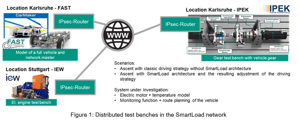
These virtually linked and thus distributed validation enables the know-how to be used directly at the appropriate locations and avoids the time-consuming gathering of all subsystems at a central location. Thus, each discipline can work in its own domain and can adapt and revise components as required. Having different test benches inside the SmartLoad network, enables the test of various test cases. Examples of two applied test cases are named in figure 1. The gear test bench, real-time full vehicle simulation and electric engine test bench are linked via IPsec-Router to each other. Using this virtual private network with encrypted messages allows a round trip time of 10ms in average. The vehicle simulation sends the set torque to the gear test bench. The resulting torque is sent to the electrical engine test bench. The torque generated by the engine is then send back to the vehicle simulation.
The efficient use of the distributed validation depends on the UseCases, components and functions to be tested. Model-based Systems Engineering enables structuring and linking different elements and their fore helps to identify the validation environments that meet the demands based on the scenario in focus.
A new approach to validate highly automated vehicles: The SmartLoad Structure
Starting with a literature review, we build on existing methods to structure elements in the context of automotive engineering and product development. Based on standards like ISO 26262 and methods like A-SPICE, 68 relevant requirements for a new method are collected. This is achieved by connecting sources, requirements and the derived elements with a Model-based Systems Engineering approach (MBSE).
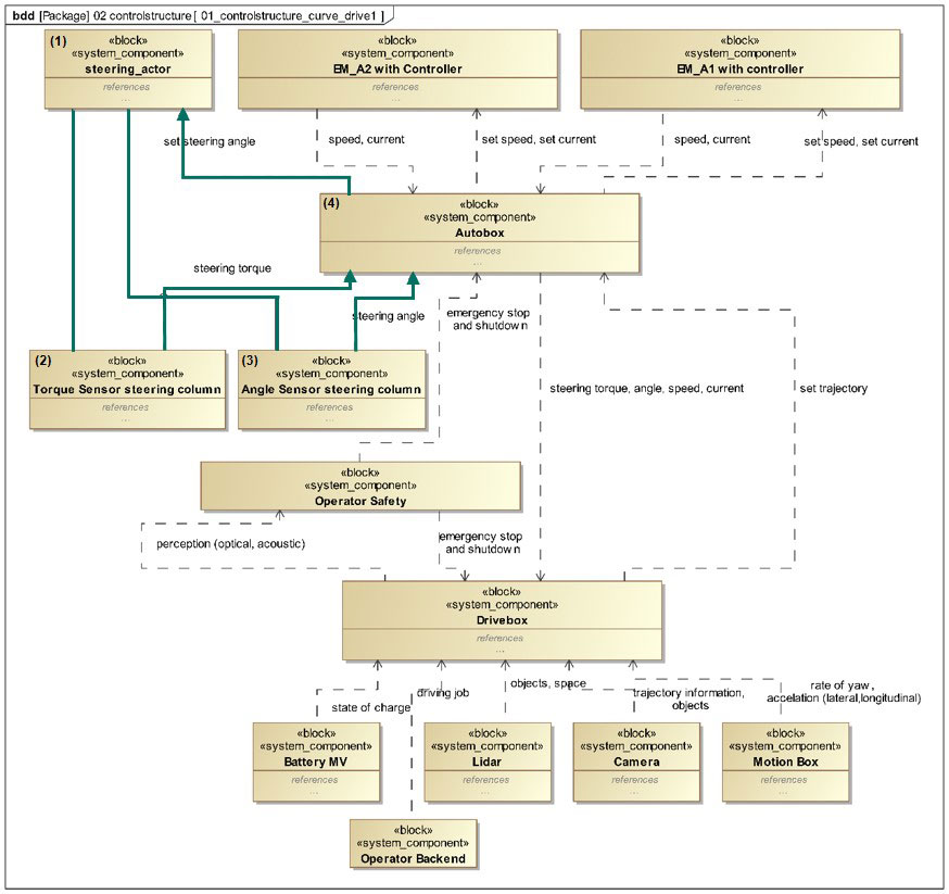
By considering the three safety dimensions in automotive industry: functional safety, Safety Of The Intended Functionality (SOTIF) and Cyber Security (ISO-SAE AWI 21434) (Schnieder und Hosse 2020), our focus lies on the integration of functional safety and SOTIF in the new method. This is partly achieved by using the method Systems Theoretic Process Analysis (STPA) and linking (validation) elements to STPA control circuit elements like hazards. Figure 2 highlights a control loop that can be identified and linked to UseCases. Components like steering actor (1), sensors (2, 3) or the Autobox (control unit) (4) exchange data, information and matter. This results in a control loop, which enables the identification of possible failures. In this example, the Autobox sends a set of steering angles to the steering actor. Sensors identify the steering torque and the angle of the steering shaft and transmit it back to the Autobox. The control loop can be used and modeled on different system levels. For example, inside the Autobox a controller regulates the adjustment of the target steering angle. As shown in figure 2, multiple elements need to be modeled and connected. Integrating the STPA in the SmartLoad Structure helps to identify UseCases specific hazards in an early stage. In addition, it enables in MBSE the linkage and therefore traceability of different elements. This allows identifying redundancies in functions and components.
Based on a specific UseCase like an uphill drive, partial UseCases can be determined. They describe individual aspects of the vehicle application and enable suitable scenarios to be set from a catalog. These scenarios describe the loads, boundary conditions and requirements for the individual functions of the vehicle. Thus, the entirety of the UseCase can be broken down to individual describable and testable aspects. In addition, by varying parameters, tests may emerge that consider previously unknown scenarios by means of ISO26262 extended by the SOTIF standard. With the help of the determined boundary conditions and requirements, the explicit validation tasks can be defined and thus a validation environment can be selected and/or set up. With the traceability, all interacting elements and UseCases can be identified when a requirement or component is changed. Thus, changes in the boundary conditions and, if necessary, changes in the functions can be determined directly and the necessary validation tasks can be derived.
In result, the distributed test benches in the SmartLoad network supports the validation of highly automated electric vehicle subsystems. MBSE approaches, including methods like STPA, supports the traceability of different elements with focus on validation. This enables UseCases and scenario specific development and validation.
Literature
Albers et al. 2014 Albers, A.; You, Y.; Klingler, S.; Behrendt, M.; Zhang, T.; Song, K. (2014): Supporting Globally Distributed Product Development with a New Validation Concept, in: Procedia CIRP 21 (2014), S. 461–466, https://doi.org/10.1016/j.procir.2014.03.142
Schnieder und Hosse 2019 Schnieder, Lars; Hosse, René S. (2019): Leitfaden Safety of the Intended Functionality. Wiesbaden: Springer Fachmedien Wiesbaden.
Acknowledgements
This work has been supported by the Federal Ministry for Education and Research (BMBF) in the project “New methods to increase the reliability of highly automated electric vehicles (SmartLoad)” with the funding reference number: 16EMO0363.