News


News from cti-symposium.world
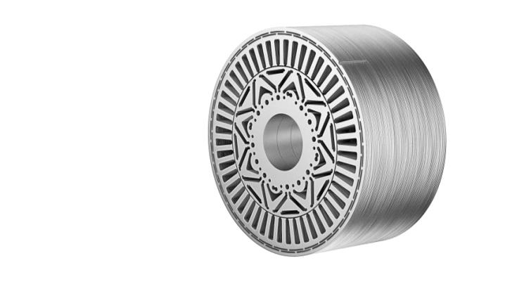
ElringKlinger MetaloBond™
ElringKlinger MetaloBond™ is a lamination stack technology using a full face glue system with high sealing capability to support direct rotor and stator cooling for increased e-motor performance. With increasing rotation speed and less installation space in advanced electric engine concepts, heat becomes more and more an issue.
Continue reading
ElringKlinger MetaloBond™
ElringKlinger MetaloBond™ is a lamination stack technology using a full face glue system with high sealing capability to support direct rotor and stator cooling for increased e-motor performance.
With increasing rotation speed and less installation space in advanced electric engine concepts, heat becomes more and more an issue.
The best way to cope with this issue is to avoid heat generation by reducing electromagnetic losses, e.g. in the iron core. A further important approach is to use an efficient direct cooling system to get heat out of the system and therefore increase continuous performance of the electric motor significantly.
ElringKlinger is very experienced to produce materials < 0.30 mm. The target is to reduce the eddy current losses in the system and by doing so, reducing the generated heat.
The packages produced with the MetaloBond™ technology achieve good values in strength and setting behavior.
MetaloBond™
Tensile lap shear strength (EN1465) 22 N/mm²
Peel resistance (EN1464) 3,4 N/mm
As a further approach, a direct cooling system can be used to remove heat. If the direct cooling system shall be designed within the iron core, a reliable and lifetime durable sealing between the single layers of the iron core must be ensured.
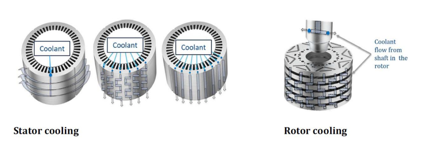
The ElringKlinger MetaloBond™ technology guarantees a high sealing capability. Due to its clear focus on sealing performance, it allows more design freedom versus other full face glue systems on the market.
With MetaloBond™ made by ElringKlinger, cooling channels can be placed with a minimum distance to the perimeter and still seal pressures up to 200 bar, even under thermal cycling and thermal shock conditions.
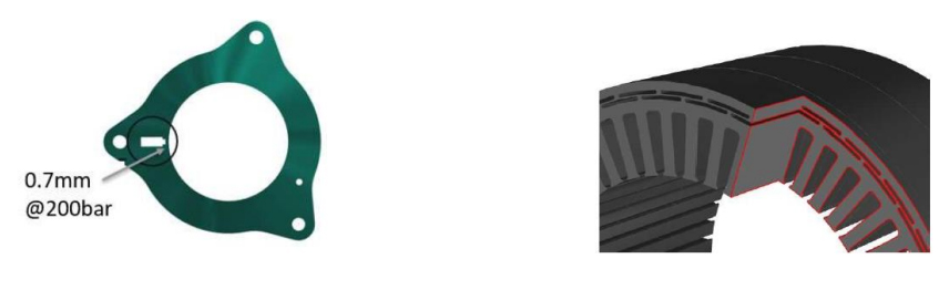
This allows to place cooling channels where they are needed. Either close to the hot spots or close to the perimeter to reduce interruption of magnetic flux. The result is an efficient cooling system with an increase in continuous performance.
As a full-service supplier, ElringKlinger is able to support you with the full range of services from heat flux calculation, lasered and stamped prototypes to fluid flow testing with thermal cycling or shock.
We are looking forward to meet you at our booth no. A7 at CTI in Novi!
Multi-vehicle driveline fluids
A smart way to meet the service fill requirements of multiple OEM specifications. OEMs in North America are increasingly fitting stepped automatic transmissions with eight or more speeds into their light-duty vehicles as they look for fuel economy improvements. However, the wide variety of different types of transmissions in the light-duty parc means the number […]
Continue reading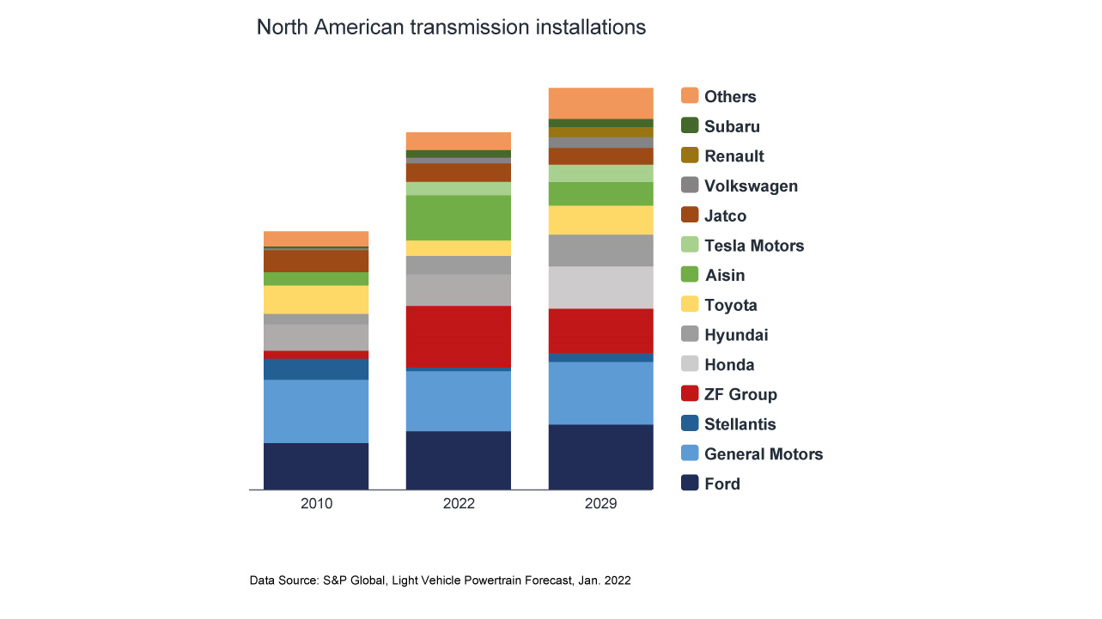
Multi-vehicle driveline fluids
A smart way to meet the service fill requirements of multiple OEM specifications.
OEMs in North America are increasingly fitting stepped automatic transmissions with eight or more speeds into their light-duty vehicles as they look for fuel economy improvements. However, the wide variety of different types of transmissions in the light-duty parc means the number of fluids required to meet the full range of service fill requirements is expanding. This article explains how multi-vehicle driveline fluids, formulated to meet a wide range of OEM specifications, can bring a number of benefits to this increasingly complex market.
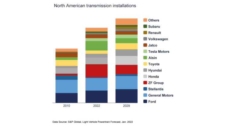
The North American light-duty vehicle parc is continuing to grow – reaching an all-time high of more than 280 million in 2022. And, as OEMs look for technology to help improve fuel economy, the number of different types of transmission in use is also continuing to grow. Over time, as fuel economy mandates have been tightened, the market has transitioned away from the once popular four, five and six speed automatic transmissions and is now dominated by those with eight or more forward speeds. The average age of light-duty vehicles in operation in this region is reported to have risen to more than 12 years. This means there are a huge number of vehicles in the market with vastly different service fill transmission fluid requirements.
An interesting trend we are seeing in this region is the increase in the number of installations from OEMs outside of North America, in particular from Japan and Europe. In addition, transmission hardware is now even more complex and compact than in the past.
This diversification means that along with the JASO 1-A 13 and 1-A 13-LV, that combine critical elements of several OEM specifications into one, there are a growing number of OEM fluid specifications designed to ensure the continued protection of their specific transmissions.
North American service fill market
Changes in the vehicle parc mean the demand for service fill fluids in North America is continuing to evolve.
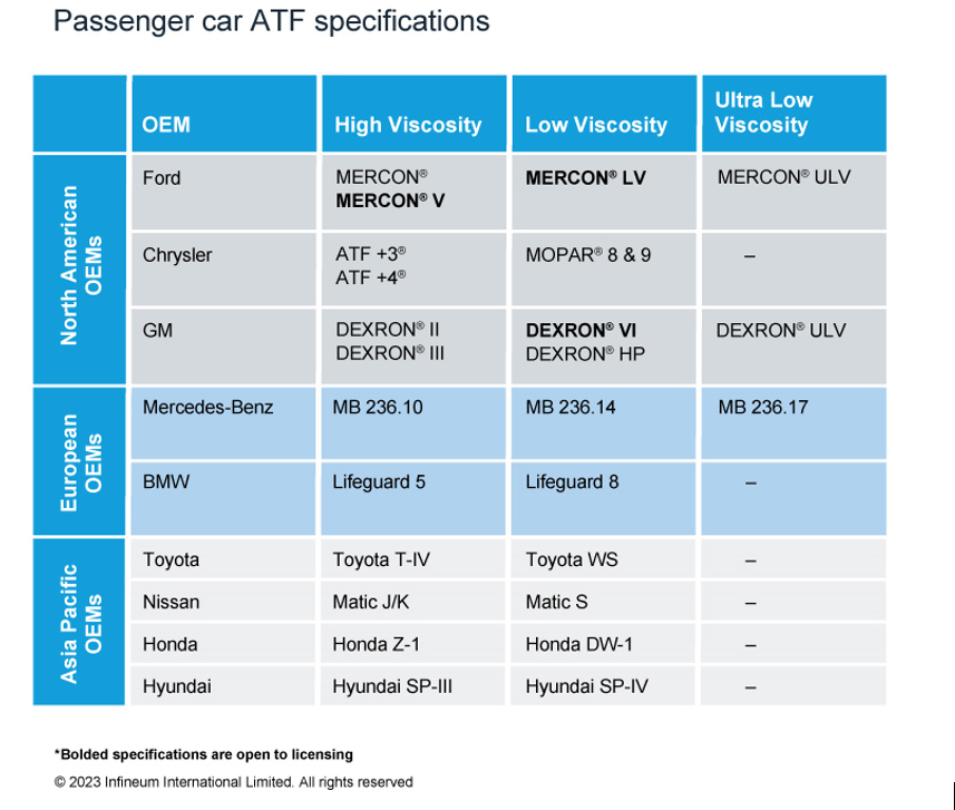
Over the years we have seen, and continue to expect, a steady decline in the use of GM DEXRON® III, Ford MERCON®/MERCON®V and Chrysler ATF+4® automatic transmission fluids (ATF). These tended to be higher viscosity fluids that covered older vehicles, most of which are now out of warranty.
On the growth side, we expect to see more demand for both DEXRON®VI and MERCON®LV low viscosity fluids.
The growing numbers of import vehicles with different OEM ATF specifications make a multi-vehicle solution attractive, especially for vehicles out of warranty. This is especially the case for quick lube and service shop operations that need to service a wide range of vehicles without carrying stock of multiple fluids. And, not surprisingly, we can see exciting opportunity and growth in this multi-vehicle transmission fluid market segment.
The benefits of multi-vehicle fluids
Currently more than 100 ATF types are available in the North American market. This proliferation means a single multi-vehicle fluid can offer significant advantages to users looking for versatility, performance and convenience for light-duty applications. It is understandable that there is some scepticism around the use of multi-vehicle ATF since it is not licensed. However, Infineum products have been proven in the market, successfully delivering a fine balance of friction and oxidation control on the road in consumers’ vehicles for more than 10 years.
Infineum multi-vehicle ATF cover 99% of all the latest and legacy light-duty planetary gear transmissions on the roads today.
Multi-vehicle fluid technology is designed to cover the needs of the ageing and diversifying North American car parc. In terms of its advantages, it delivers the balanced frictional performance and hardware protection for the latest domestic and import transmissions, provides exceptional performance in older designs and acts as the perfect complement to OEM licensed ATFs.
Multi-vehicle ATF is formulated with advanced additives that help protect against wear, oxidation, and deposit formation. It can also provide smooth shifting and consistent performance across a range of temperatures. This can extend the life of the transmission as consumers keep their vehicles for longer and longer.
The single additive package can be used to blend in high and low viscosity formulations without sacrificing hardware protection and delivers performance attributes including:
- Friction control: finely tuned to enable balanced torque transfer and smooth shifting
- Friction durability: maintain anti-shudder durability enabling smooth acceleration over time
- Oxidation stability: increase oil life and reduce sludge
- Shear stability in high and low viscosity environments
Infineum has run a comprehensive test programme, including field, dynamometer and rig tests, in a range of different transmissions to assess multi-vehicle fluid advantages in some of the key performance areas and to prove all the various ATF applications.
Opportunities for growth
Formulation flexibility is of growing importance, particularly as base stock supply remains tight and prices volatile. Here Infineum products can be formulated in many Group III base stock options, or Group II & III base stock systems with up to 50% Group II. In addition, as consumers look for more sustainable product options, this formulation flexibility has enabled us to start to integrate both re-refined and bio-based base stocks into our driveline portfolio. Also, having a dynamic single fluid that satisfies a range of vehicle needs can contribute towards sustainability goals via the simplified logistics, storage, and handling required to get the right fluid to the right service areas.
Clearly, low viscosity multi-vehicle ATFs can offer significant advantages to users looking for a single fluid to cover a range of light-duty applications. They not only deliver the balanced frictional performance and hardware protection for the latest domestic and import transmissions and provide additional protection to older transmissions but also give blenders the flexibility they need to meet the requirements of all their target markets.
Infineum multi-vehicle fluid technology performance is proven in millions of transmissions currently on the road.
Proven multi-vehicle ATFs provide fluid marketers with a strong customer value propositions including reduced stock holding, increased flexibility and less potential for misapplication and offer an exciting opportunity for future growth in North America and potentially beyond.

More compact, more efficient, more sustainable, more affordable… what’s on your wish list for the perfect e-Drive?
Progress never stops. With electric drive technology evolving rapidly, developers can now meet customer requirements even more precisely and comprehensively, while higher efficiency also increases the performance and range of battery-electric drives. So what’s next? One thing’s for certain: With customers seeking more independence and flexibility, plug-in hybrid drives are staging a comeback.
Continue reading
More compact, more efficient, more sustainable, more affordable… what’s on your wish list for the perfect e-Drive?
Progress never stops. With electric drive technology evolving rapidly, developers can now meet customer requirements even more precisely and comprehensively, while higher efficiency also increases the performance and range of battery-electric drives. So what’s next? One thing’s for certain: With customers seeking more independence and flexibility, plug-in hybrid drives are staging a comeback.
CTI Symposium USA – covering all the angles with the customer in mind
In twelve Deep Dive sessions, specialist lectures will cover the latest electric drive systems and their key components. In the plenum, prominent representatives from OEMs, suppliers and universities will discuss their strategies and technologies for tomorrow’s CO2-neutral mobility. The goal: Advanced automobiles that, ultimately, only need to convince one person – the driver.
Raising many bars. And clearing them all.
“With our next generation eDrives, Magna aimed to set new standards in KPIs such as efficiency, power-to-weight, torque-to-weight, power-to-price and torque density,” says Daniel Lindvai-Soos (Magna Powertrain, Austria). Further goals included a drop-in solution on the hardware and software level, higher product and production sustainability, and improved system integration. As the key figures he presents will show, the company has certainly succeeded.
Magna’s NextGen drive is significantly lighter and smaller than the current version. The 29% reduction in the Z-dimension is particularly important, since it enables horizontal and vertical integration into the rear and front vehicle space. The new drive offers 94% efficiency in WLTC, and 93% including real-world highway driving. This improves efficiency over a wide speed range, and expands application flexibility. The new eDrive uses significantly less aluminum and rare earth material, and the CO2eq for production has been cut by around 25%. Among the new technologies making their debut in the NextGen drive are the HV Embedding SiC Power Modules. These reduce electrical losses and improve efficiency. Daniel Lindvai-Soos will also be giving an overview of software-oriented advantages such as OPP (optimized pulse patterns), the thermal operating strategy, active peak load damping, state-of-health monitoring, and other end-user functions. A digital twin is part of the new Magna NextGen drive. It simplifies integration into the operational strategy, and supports the ‘drop-in solution’ approach.
“What could we do better?” How Toyota learns from its competitors.
Space is a valuable commodity in battery electric vehicles (BEVs), and customers want vehicles whose drivetrain components all combine high performance with efficient use of space. The study presented by Jaret Villarreal (Toyota, USA) will focus on the power density potential of compact, single-axle powertrain systems. The study began by reverse-engineering a competitor’s geartrain. Using this model, an in-house optimization workflow then explored the feasibility of reducing its size further, without compromising on standards.
Jaret Villarreal will provide insights into the workflow and software used, and will discuss the results of the optimization. The study clearly demonstrates the possibility of considering optimization at earlier development stages for BEV transaxles, and also highlights the need for continuous improvement. Using the latest technological advances, Toyota engineers can now pursue multiple competing goals simultaneously, all in specific workflows. These include efficiency, NVH, durability, size and cost. As a result, they can create designs that offer customers the best possible driving experience.
Control losses with high-speed motors? Not with Surface Acoustic Wave (SAW) sensors.
There is a growing trend towards high-speed, high pole count motors. But to maintain controllability, they require higher switching frequencies from the power electronics. As David Hind (Drive System Design, UK) and Ryan Maughan (Transense Technologies, UK) will explain, current solutions can quickly reach their limits here. Field Oriented Control (FOC) has a high computational burden, while Direct Torque Control (DTC) suffers from the poor accuracy of the torque estimators used.
David Hind and Ryan Maughan will be presenting a new method that uses SAW (Surface Acoustic Wave) sensor technology to overcome these shortcomings. By embedding SAW sensors, developers can obtain robust, precise, high-speed readings of torque and shaft temperature in real time. SAW sensor technology has already proven itself in motorsport and aviation, and is suitable for use in production motor drive systems. “Transense Technologies has been working with Drive System Design (DSD) to explore the potential of integrating torque sensors into the control loop of electric motors,” say Ryan Maughan and David Hind. “Using DSD’s extensive simulation capabilities, new control algorithms can be implemented and assessed.” The speakers will discuss the findings of this work, and will demonstrate an improved method of motor control using SAW torque measurement feedback. Specifically, they will quantify the reduction in computational overhead compared to FOC. This can indicate what increase in inverter switching frequency – and hence potentially motor fundamental frequency – can be achieved from a motor control perspective.
Torque management systems – the masters of traction and driving dynamics
For maximum driving pleasure and safety, ample torque alone is not enough. You also need to distribute that torque optimally between the wheels and axles and convert it into traction, always in line with specific driving scenarios. Modern electric drives can use various torque management systems (TMS) to achieve this aim. But which works best in which specific case?
This is the question that Josefin Frisk (BorgWarner, Sweden) will be addressing in her lecture. As EV models become more diverse, the range of drive architectures for different segments and performance levels is expanding too. In the past, several TMS implementations have been proposed – one electrical machine per wheel, for example, or an additional electrical machine to supply differential torque, carefully actuated friction clutches to replace the differential, or an electrically controlled limited-slip differential. All these TMS architectures provide additional degrees of freedom for the vehicle controls. They also affect energy consumption and performance in different ways, change how the vehicle feels for the driver, and how it performs under challenging driving conditions. In addition, they offer potential for differentiation, and significantly improve safety. As you might expect, each architecture involves an inherent trade-off. In her presentation, Josefin Frisk will quantify and explain the differences between various TMS options for BEV architectures in terms of energy consumption, vehicle performance, packaging and cost. And in the process, she will answer the question we asked at the beginning.
A surprising comeback: What’s next for hybrid drives?
There’s no missing the resurgent interest in hybrid drives, as a glance at our agenda at CTI Symposium USA will confirm. With high-ranking representatives from leading OEMs, the panel discussion on this topic promises to yield interesting insights. In the plenary session, hybrid pioneer Toyota will be sharing details of its development work on the new hybrid system for the Camry. And last but not least, hybrid drives will feature in individual contributions to the Deep Dive sessions.
Advanced hybrid systems – the best of both worlds
There are good reasons to favor hybrid drives as a bridging technology. As Aditya Dattawadkar (Schaeffler Group, USA) will point out, most US customers want an electric vehicle that won’t make them alter their lifestyle too much. They are used to driving big vehicles for hours on end with just short breaks before they resume their journey. By offering the flexibility customers seek in terms of range and energy sources, hybrids tick all these boxes and deliver the best of both worlds: ICE and BEV.
Business-wise, hybrid vehicles are the ideal way to keep using existing technologies while simultaneously promoting the switch to pure-electric drives. Some engines and transmissions are the result of decades of development work, and are highly efficient, cost-effective and reliable. As Aditya Dattawadkar will explain, Schaeffler is working hard on hybrid systems that can be flexibly adapted to customer needs. The company benefits from the knowledge gained from ICE drivetrains, and also from advances in electric motor development. Schaeffler has several ideas in production, and more at advanced stages of development. In his lecture, Aditya Dattawadkar will showcase some of the latest hybrid vehicle technologies, then address the growing demand for hybrid systems and show ways in which it can be met. His application fields will range from passenger cars to pickup trucks and light commercial vehicles.
Integration in perfection – a pioneering approach for a PHEV P3 pickup truck
What’s the best way to integrate a high-performance P3 hybrid system in a 4WD light truck? The research paper presented by Larry Pritchard (BorgWarner, USA) gives a surprising answer: “Put it in the transfer case!”
This innovative integration approach eliminates the need for conventional planetary transfer case range sets, and significantly simplifies packaging. The primary goal of the research study was to enhance the electrical proficiency of these hybrid systems, and specifically to extend their electric-only range. The aims are to reduce reliance on combustion engines, and to achieve higher levels of electrification. The optimized sizing of electric drive train components, including 400 and 800 volt systems, plays an important role.
Larry Pritchard will present key advantages and interesting technical highlights of the P3 hybrid drive system. These include on-demand front axle braking energy recoupment, which the integration of the P3 system into an active transfer case makes possible; using the hybrid drive as a power generator and energy source at remote worksites, and the fact that a PHEV P3 pickup truck can meet ambitious emissions targets. The research will help developers to build efficient, versatile light trucks that satisfy users to the full in terms of driving performance, independence and sustainability.
CTI Symposium USA – three days that make a difference
Discover an informative and inspiring program on May 15th and 16th! Follow the specialist lectures in twelve Deep Dive sessions. Play an active role in the plenary discussions, and explore the latest developments at CTI SYMPOSIUM EXPO. Enjoy a test drive with CTI RIDE & DRIVE – and grow your business network at our CTI NETWORKING NIGHT.
Welcome to CTI Symposium USA!
eS4500i: Highly Integrated Electric Drive Unit for Multiple Applications
Marco Silvestri, Chief Engineer, Dana Incorporated Across all our actions, we never lose sight of a guiding vision toward a zeroemissions future. This has powered our first-mover advantage in electrification. At Dana, we strategically invest in technical competence − designing, engineering, and manufacturing the components of a complete e-Propulsion system in-house. These innovations include efficient […]
Continue reading
eS4500i: Highly Integrated Electric Drive Unit for Multiple Applications
Marco Silvestri, Chief Engineer, Dana Incorporated
Across all our actions, we never lose sight of a guiding vision toward a zeroemissions future. This has powered our first-mover advantage in electrification.
At Dana, we strategically invest in technical competence − designing, engineering, and manufacturing the components of a complete e-Propulsion system in-house. These innovations include efficient EV systems and new electrodynamic products like motors, inverters, controls and software, battery cooling systems, and metallic bipolar plates for fuel cell applications.
 The legislation for pollutants and emissions is driving OEMs to design their reduction programs to align with aggressive timelines — accelerating the adoption of electrification. These mandates, coupled with corporate commitments from OEMs, will significantly increase the demand for electrified vehicle architectures, the main components of a Battery Electric Vehicle.
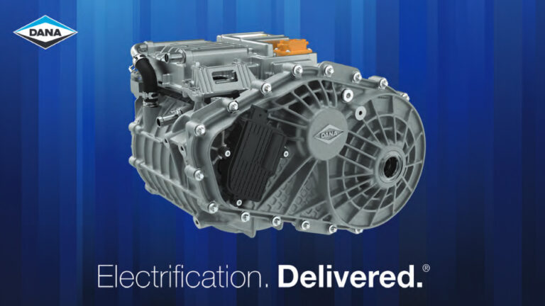
Dana’s solution is the Spicer® Electrified eS4500i e-Drive Unit − a highly versatile 3-in-1 electric drive unit (EDU) that converts the stored electrical energy from the battery into mechanical power to the wheels.
eS4500i Platform
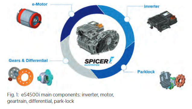
Utilizing competencies from Dana’s global network of technology centers, the highly integrated eS4500i comprises an inverter, motor, one-speed geartrain, open differential, and optional park-lock.
The thinking behind the eS4500i was really to provide more than a single EDU. What was needed was a versatile platform offering multiple ratios and integrated design of motor and gearbox while also taking into consideration efficiency, optimized packaging space, and lower weight.
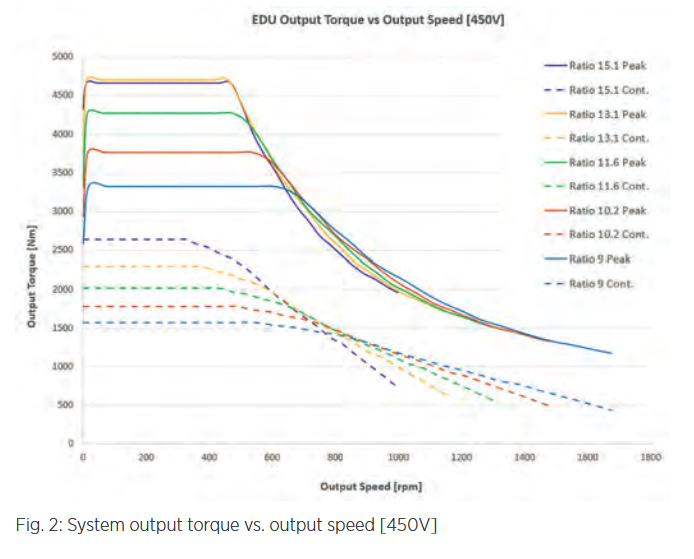
To cover multiple applications, five different ratios were designed (macrogeometry) with the same center distances, same gear width, and similar envelopes diameters also recombining the same gears to reach five different ratios.
In this way, with a unique design of the housing and bearings, the eS4500i can host five different gear-trains to be able to match different vehicle requirements in terms of maximum torque and speed. From figure 2, it’s appreciable the spread of torque and speed that the system can cover with the five different ratios options. A limitation of around 4,500 Nm (as max nominal output torque value) has been decided for ratio 15.1 and 13.1 because of match with other Dana products but useful in case of demanding vehicle gradeability and high continuous torque.
Highly Integrated Layout
The design of the gearbox and the motor was improved by integrating the components as much as possible to provide a light, compact, and power-dense EDU.
For the eS4500i, it has been decided to have a highly integrated design between the motor and gearbox to save weight and to improve the power density.
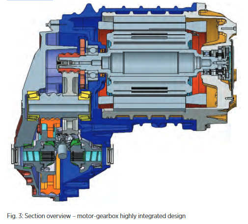
Only three housings compose the structure of the EDU and shape two separate environments: a dry one for the motor and a wet one for the oil-lubricated gearbox.
Referring to figure 3, from right to left:
The motor back-case supports the rear motor bearing and becomes the seat for the stator and the internal side of the motor cooling jacket. The helical cooling path is made by die-cast molding for manufacturing efficiency.
A carrier housing supports the front motor bearing and becomes one of two gearbox housings as well as the external side of the motor cooling jacket to complete the sealed channel.
The cover housing enclosures the gearbox components.
One of the main characteristics of the highly integrated layout is the over-hanged pinion gear directly mounted on the head of the rotor shaft. Between the pinion gear and the motor front bearing, there is a parking gear.
The layout is completed by an intermediate shaft and an open differential, both supported by taper roller bearings.
This new layout reduces the interfaces between the gearbox and the motor to achieve a precise axial centering of the gearbox with the output shaft of the motor. This also allowed a significant reduction of components like having only two bearings on the input axis, a reduction of the number of housings and a significant a reduction of fasteners.
The EDU is completed by the inverter that is direct-mounted on top of the motor with the high voltage connections passing through the back housing.
The park-lock adds another degree of flexibility because it can be added or removed on customer request. This park-lock option is already patented and in series production, with a mechanism layout now upgraded with a new smart actuator.
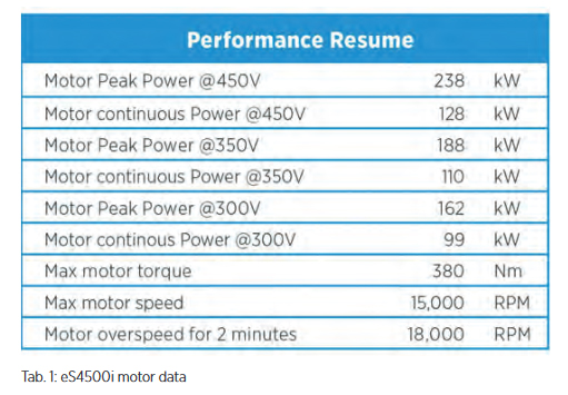
Motor and Inverter
The eS4500i is powered by a propulsion system composed of an asynchronous dry 450V motor and with a Dana 2nd generation directmounted inverter.
The propulsion system is cooled by water-glycol and the theoretical performance curves are shown in fig. 5 at 65°C coolant temperature.
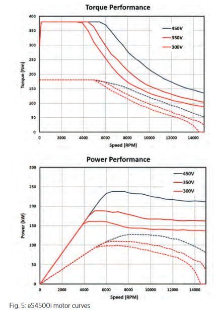
Since this propulsion system is for a medium voltage (450V) application, Dana decided to use the latest IGBT module technology for this inverter over the newer SiC MOSFET technology. This allows the use of our proprietary Reflex gate driver technology to achieve the most cost-effective solution for this voltage range.
Conclusion
As a Tier 1 supplier, Dana offers its new eS4500i EDU, an off-the-shelf solution on the path to electrification, with a compact and light package for a wide range of applications.
The eS4500i is equipped with the well-known Dana differential from a robust off-road heritage, with an optional park lock system.
Dana is offering its all-new configurable off-the-shelf eS4500i EDU to a multitude of segments and applications. This work is the result from the synergy between the different technical centers and other global Dana branches, putting together different competencies. With its power density, reliability, and cost competitiveness, this product will contribute to our customers’ success on the path to electrification.

JJE 2-Speed Electric Beam Axle for Medium Duty Truck
Ping Yu, CEO, Chief Engineer, Founder, Jing-Jin Electric Dr. Yang Cao, Transmission Senior Supervisor, Jing-Jin Electric The electrification of medium duty truck grows rapidly. JJE’s newest electric beam axle family can cover up to 11T (or class 6 in North America) trucks, including single-speed and 2-speed systems. Multiple advanced technologies are integrated into the electric […]
Continue reading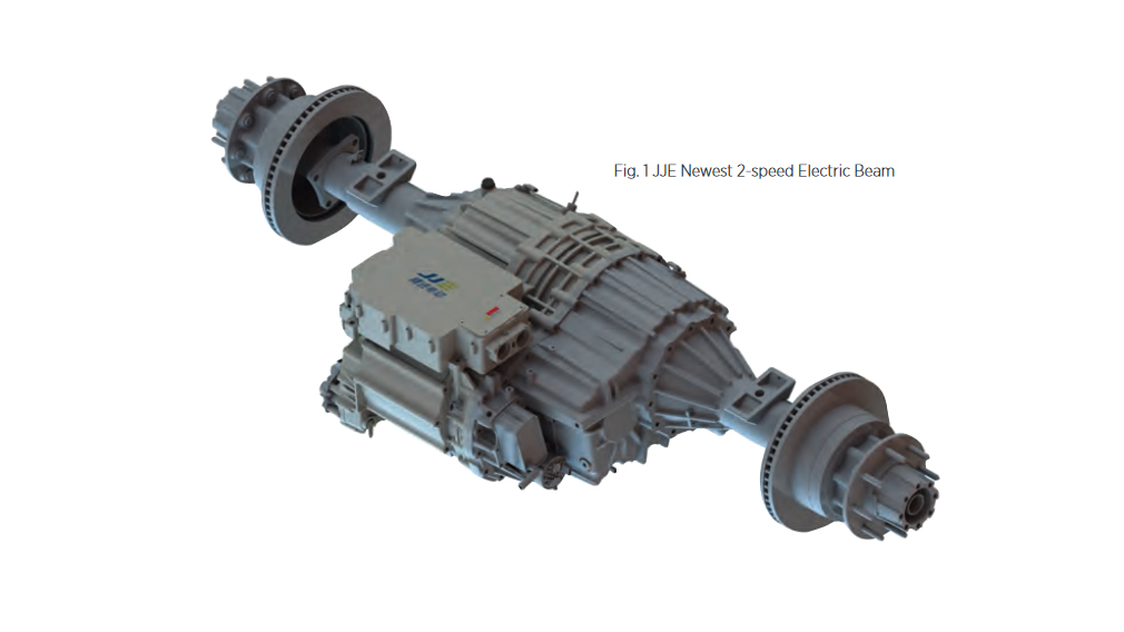
JJE 2-Speed Electric Beam Axle for Medium Duty Truck
Ping Yu, CEO, Chief Engineer, Founder, Jing-Jin Electric
Dr. Yang Cao, Transmission Senior Supervisor, Jing-Jin Electric
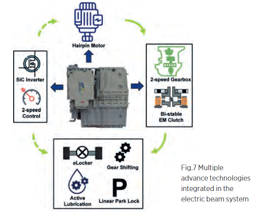
The electrification of medium duty truck grows rapidly. JJE’s newest electric beam axle family can cover up to 11T (or class 6 in North America) trucks, including single-speed and 2-speed systems. Multiple advanced technologies are integrated into the electric beam system, such as bi-stable electromagnetic bi-directional shifting clutch, bi-stable eLocker, linear park lock system, and active cooling and lubrication. These functions’ control is all in the electric beam axle’s inverter, which is mounted on the axle. 800V, high power hairpin motor and SiC inverter are used to produce strong capacity, and high efficiency across wide operating range.
The 2-speed axle features a high efficiency hair-pin electric motor, a 400kW SiC inverter with “safe towing” feature, electro-magnetic shifted 2-speed gearbox, with neutral position that also serves as a disconnect, bi-stable differential eLocker, linear park lock system. With 2-speed gearbox, the beam axle’s wheel-end torque is up to 15,000Nm, and the maximum vehicle speed is over 160km/h. Integrated design for motor and gearbox reduces the axial length of the system.
JJE’s 2-speed beam axle features high performance and high output speed, with little power degradation at high speed. Its efficiency is high over a wide speed range – especially in comparison to a single speed axle thanks to the 2-speed gearbox.
Fig. 2 JJE Electric Beam at the Rear of a Truck Demonstrator
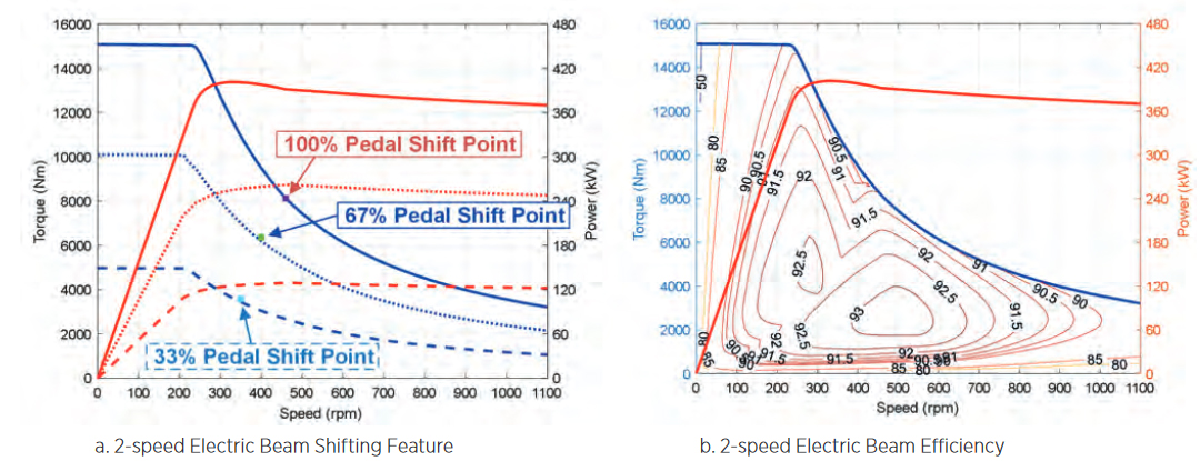
Fig. 3 JJE 2-speed Electric Beam Performance
Electric Motor
JJE has a mature hairpin motor designs to cover performance requirement of wide range of vehicles. For this electric beam axle system, the electric motor’s peak power reaches 420kW at 650Vdc, with 97.4% maximum efficiency, and over 90% of the efficiency map is above 88%. The water-oil combined cooling allows the electric motor to produce high continuous power.
2-speed Gearbox
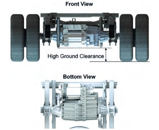
The 2-speed gearbox provides high launch torque, high vehicle speed and high efficiency over broad duty conditions, and helps contain motor’s top speed for better reliability and durability. It also broadens high efficiency operating range, and significantly reduces thermal loading in the system at high speed. A 2-way, bi-stable electromagnetic clutch is used for shifting between 1st gear and 2nd gear, with neutral position. The neutral position is a natural “disconnect”. Combining this rear axle with neutral with a constantly powered front eAxle, the vehicle efficiency can be improved. JJE’s patented DirectFluxTM Bi-stable eLocker enhances functional safety of the locker and eliminate the power consumption. Proven park lock system is implemented on the motor shaft, or the “lowest torque” point of the system. An oil pump provides active oil lubrication, which allows low oil level in the gearbox, reduces gear churning loss.
SiC Inverter
The electric beam axle has an 850V SiC inverter integrated on it, with functional safety level up to ASIL D. Multiple functions − such as motor control, differential locker control, 2-speed transmission control, park lock control − are integrated in the inverter, taking advantage of inverter’s high functional safety control platform. With backup power supply, the inverter enables “safe towing”, a feature highly desired by customers. It is a critical safety redundancy in the event of 12V power supply loss.
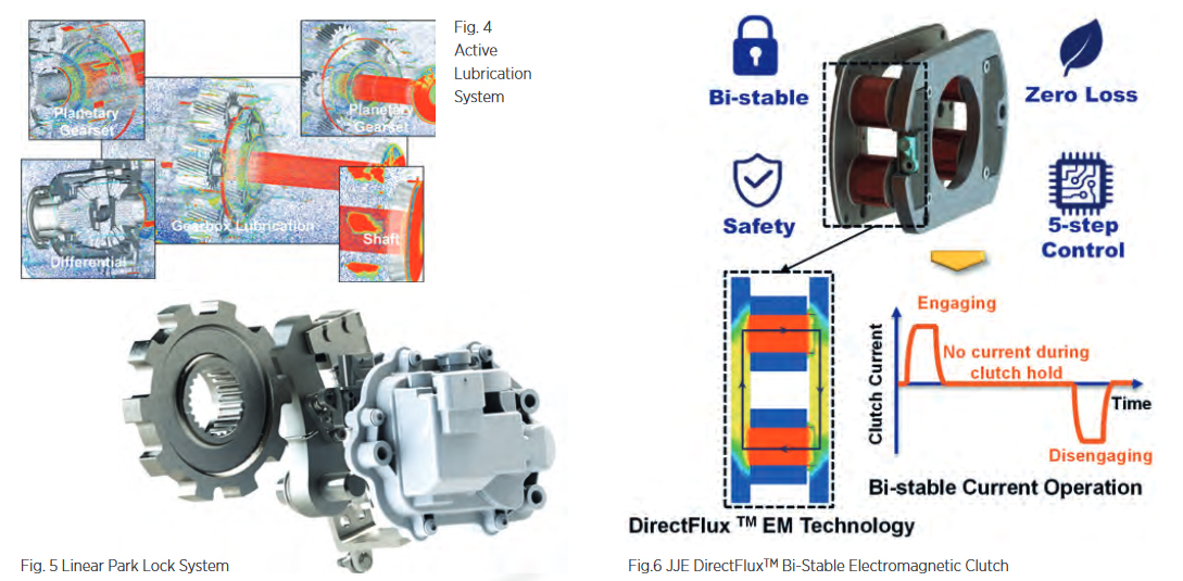
DirectFluxTM Bi-stable Electromagnetic Clutch
Patented bi-stable electromagnetic clutch is JJE’s one of the most advanced technologies. It is used for gears shifting and locking the differential in the electric beam axle system. This technology has been successfully used as a differential locker in JJE’s 300kW SiC EDM and as a disconnect in JJE’s new AWD EDM.
DirectFluxTM electromagnetic clutch takes advantages of its innovative magnetic circuit design. Compared to the more conventional reluctance flux magnetic circuit design, the DirectFluxTM design greatly reduces flux leakage, and therefore utilizes magnetic flux more effectively to generate force. However, the conventional reluctance flux design cannot avoid magnetization of parts near flux circuit, or “flux leakage”, which causes less effective utilization of magnetic flux. As a result, DirectFlux acts 2-3 times faster than a reluctance flux design.
The bi-stable clutch is inherently fail-safe as it won’t change state in the event of loss of power. This feature gives bi-stable clutch a higher safety level than mono-stable clutch. For differential locker, it will prevent sudden locker release due to the loss of power or control failure. For transmission shift, it will prevent gear unexpected back to neutral which will lead the vehicle loss of traction. On energy consumption side, the bi-stable clutch’s feature of “zero holding current” eliminates holding current and in turn achieves zero power consumption.
In the development stage of an electromagnetic clutch, a software platform based on several simulation tools is built for more precise simulation result. This platform covers signal, electric, electromagnetic, and mechanical aspects. It addresses almost every detail, including software control, PCB layout, electromagnetic transient simulations, multi-body dynamic simulations, and strength. It provides strong support to the clutch’s development.
Electric beam axles are designed for pickup trucks, light duty trucks, or medium trucks. As the beam axles get electrified, a lot of traditional technologies no longer fit. JJE takes advantage of its knowledge in electric drive, strong R&D capabilities on motor, inverter, transmission and clutches and expertise in system integration, creating the 2-speed electric beam axle for the large medium truck segment.

Overcoming Challenges to High-Speed Electric Motors
Craig Renneker, Vice President Innovation, AAM While the EV growth rate remains uncertain, there is little doubt that the use of automotive electric drive units must drastically increase to meet global climate objectives. This requires mass market acceptance across the full range of vehicles − size and price. A major enabler to reaching more customers […]
Continue reading
Overcoming Challenges to High-Speed Electric Motors
Craig Renneker, Vice President Innovation, AAM
While the EV growth rate remains uncertain, there is little doubt that the use of automotive electric drive units must drastically increase to meet global climate objectives. This requires mass market acceptance across the full range of vehicles − size and price. A major enabler to reaching more customers is to reduce the cost, size and mass of Electric Drive Units (EDUs), as well as the quantity of natural resources required in manufacturing.
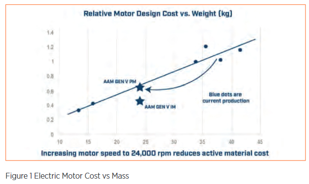
The power produced by an EDU is a product of its torque and rotational speed. Increasing the rotational speed enables power to be achieved at a lower torque. Simply put, spinning the motor faster reduces its size, mass and cost (Figure 1). The result: fewer costly materials are required, such as copper windings, magnetic steel and, in some cases, rare-earth magnets.
Traditional electric motors rarely spin to 20,000 rpm. Exceeding this level requires careful motor, gearbox and inverter design. This article discusses the approach AAM is taking to overcome various design obstacles to enable speeds up to 30,000 rpm – the speed needed to make a real impact in clean mobility and customer acceptance of EVs.
The Integrated Approach
An accessible EDU with a 30,000 rpm motor requires an integrated motor, gearbox and inverter. Each area presents specific challenges to execution and opportunities for new designs:
- Motor: pole count, rotor centrifugal forces, cooling, sealing and bearings
- Gearbox: pitch line velocity of the gear teeth
- Inverter: Switching losses
The Motor
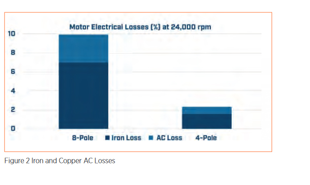
Most electric motors employ stators with 3-phase copper windings driven by sinusoidal alternating current. As the frequency of these sinusoidal currents increase, parasitic power losses in both the magnetic steel laminations and copper conductors increases. These are commonly called iron and copper AC losses. The required frequency for a 3-phase motor is determined by the motor pole count and rotational speed. Most motors today are 8-pole designs with interior permanent magnets. AAM uses a 4-pole architecture which requires half the sinusoidal current frequency of an 8-pole design. This significantly reduces iron and copper AC losses. (Figure 2)
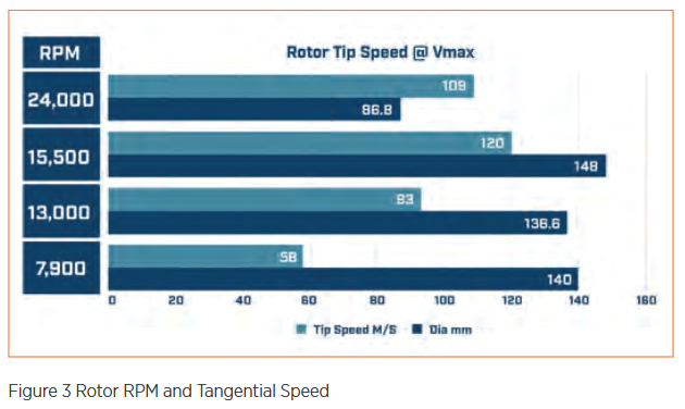
Reducing the diameter of the rotor enables higher speeds. Fortunately, higher-speed motors require less torque for a given power level, allowing a smaller diameter. As an example, the tangential speed of an 87 mm OD rotor at 24,000 rpm is lower than a much larger rotor spinning at 15,000 rpm (Figure 3). Using stress analysis of the lamination and magnet geometry, high speeds can be attained.
Smaller, fast turning motors have basic geometric challenges in removing heat. To effectively remove this heat AAM uses forced oil cooling of both the stator and rotor. A series of stamped holes in the stator laminations are arranged to form helical cooling passages around the copper windings. Oil is also pumped into the hollow rotor shaft with special heat sink features to increase surface cooling. This method reduces the heat generated in both the stator and rotor without the need for a glycol-cooled motor jacket.
AAM is employing a completely different approach to cooling highspeed rotors. Instead of pumping glycol coolant through the hollow center of the rotor requiring radial lip seals, AAM is cooling the stator, rotor and inverter with the same low-viscosity oil used to lubricate the gears and bearings. With this arrangement, no sealing is required between the rotor and gearbox elements.
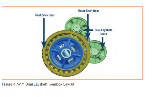
In most EDUs, a simple 2-stage helical-gear reduction is used to step motor speed down to the vehicle wheel speed. The pressure angle of the gear teeth generates a radial load proportional to gear torque that must be carried by bearings on the rotor axis. With a typical singlemesh, 2-stage helical gear reduction, bearing capability limits motor speeds to 20,000 rpm. AAM uses a dual-layshaft gearbox arrangement to balance these gear separation loads, which enables traditional small bearings to be used. (Figure 4).
Gearbox
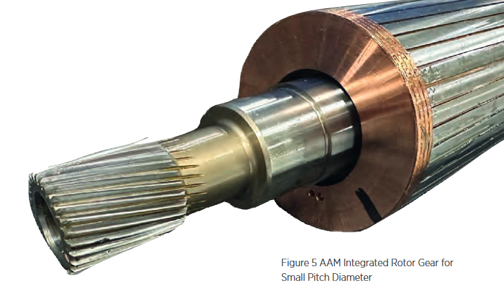
Higher motor speeds require higher gear ratios to maintain normal wheel speeds. Any ratio can be accommodated with enough successive reduction stages. However, each additional stage adds cost, mass, package space and parasitic loss to the gearbox. Typical low-speed drive units employ a 2-stage reduction. As such, it is desirable for a high-speed motor to avoid the penalty of adding a third reduction stage. The critical enabler for high ratio (up to 22:1) is keeping the first stage drive gear very small. By keeping the motor off the wheel axis AAM enables the rotor shaft drive gear pitch diameter to be very small to provide a large reduction in the first stage and reduce pitch line velocity (Figure 5)
Inverter
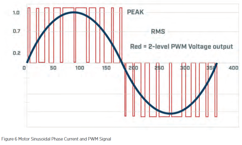
The inverter converts DC battery voltage into multi-phase AC that drives the stator of the electric motor. The frequency of the required sinusoidal current is directly proportional to the motor’s rotational speed and its number of magnetic poles. The inverter induces this sinusoidal AC to flow in the stator windings using pulse-width modulation (PWM) of the battery voltage (Figure 6). Pulse-width modulation involves solidstate switching devices that can turn on and off very quickly. Each on/off cycle results in a small amount of energy being lost within the switching device. As such, higher sinusoidal frequencies require faster switching, which increases inverter losses.
AAM’s 4-pole motor design operates at half the sinusoidal frequency of a traditional 8-pole motor. This enables the motor to spin at twice the speed with equivalent inverter switching losses.
Conclusion
AAM continues to push the limits of electric motor speed in EDUs. The company has several demonstration vehicles and one pre-production application running at 24,000 rpm, with an additional development unit producing 30,000 rpm. These designs can be produced at low cost in high volume using practical engineering solutions overcoming previously perceived limiting factors. These designs can enable the growth of EDUs into a wide variety of vehicle applications, thus creating a broader impact on carbon reduction and clean transportation. Innovations at AAM are creating efficiencies for our customers, satisfaction for consumers and an increased opportunity to positively impact our environment.
A Game-Changing Solution for OEMs and Tier 1 Suppliers:
Pressure Equalization Element Protects Transmissions During Water Crossings Volker Buchmann, Business Development Manager, Konzelmann In a world where extreme weather conditions and waterrelated challenges have become commonplace, the automotive industry faces a pivotal question: How can we equip vehicles for water crossings efficiently while saving time and resources? The answer lies in a groundbreaking innovation […]
Continue readingA Game-Changing Solution for OEMs and Tier 1 Suppliers:
Pressure Equalization Element Protects Transmissions During Water Crossings
Volker Buchmann, Business Development Manager, Konzelmann
In a world where extreme weather conditions and waterrelated challenges have become commonplace, the automotive industry faces a pivotal question: How can we equip vehicles for water crossings efficiently while saving time and resources? The answer lies in a groundbreaking innovation that is poised to revolutionize how we approach water crossings and offers OEMs and Tier 1 suppliers a transformative advantage.
Safeguarding against the elements
Throughout this past summer, extreme weather conditions occurred all over the world, with extraordinarily strong rainfalls accompanied by heavy thunderstorms and an increased risk of flash floods. When tunnels or underpasses are flooded due to continuous rain, there are often only two options: detour or wade through. Vehicle drivers tend to overestimate their vehicle‘s ability to cross water. In these situations, water or mud can quickly infiltrate the transmission resulting in a failure that only a towing service and costly repairs can resolve.
While vehicles usually are equipped with a hose construction to manage water crossings, there was no simple technical solution for wading through water. Until now. The newly designed Pressure Equalization Element (PEE), directly integrated into the transmission, prevents both positive as well as negative pressure within closed housings in electric axes and differentials, promising new perspectives for reducing product costs and time to market.
Hose construction: elaborate and costly
As mentioned, to prevent water from entering, a hose is connected directly to the transmission, providing ventilation during pressure variations. Although the hose construction is suitable for water crossings and is installed as standard, it is considered elaborate in design, resulting in time and cost-intensive assembly. Currently, there is a lack of a simple technical solution for water crossings.
The solution to this challenge is the Pressure Equalization Element (PEE), a pioneering innovation designed to fit directly into the transmission housing. The PEE houses an internal pressure-regulating valve that swiftly balances pressure differentials, safeguarding the ventilation space against contamination and the intrusion of liquids. Operating at 70 mbar, equaling a water column of 70 cm, the valve withstands exposure to gearbox oil aerosols, typical vehicle substances, and environmental materials.
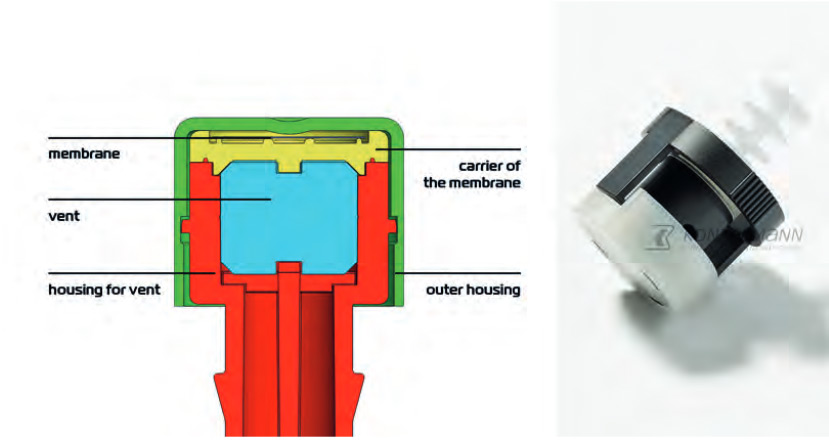
Konzelmann’s Pressure Equalization Element protects the system seals from damage due to positive or negative pressure. Source: Konzelmann GmbH
A membrane that defies liquids and contaminants
In contrast to a conventional hose system, the PEE is securely integrated within the electric axle housing.The pressure equalization valve, designed to prevent positive pressure, allows escaping gas to exit through a lateral opening in the housing while permitting air to flow in during a negative pressure situation in the housing. This air passes through an air-permeable yet waterproof Ventikon membrane. This membrane is capable of withstanding a water column of 30 meters, effectively blocking liquids as well as contaminants, safeguarding the electric axle against foreign objects.
At a defined negative pressure, the valve opens, enabling air to flow in to equalize the pressure difference. The PEE‘s membrane is thoughtfully shielded, preventing it from being coated with spray oil. Furthermore, a labyrinth-like oil separator, positioned between the valve and the electric axle‘s interior, shields the valve from direct contact with splashing oil.
Simulating real-world performance
Konzelmann, in collaboration with an OEM and a Tier 1 supplier deeply involved in transmission and differential development, has conducted in-depth analysis and established testing parameters for a dedicated testing environment. This in-house testing platform enables accurate simulation of transmission behaviour, allowing precise customization of the pressure equalization valve to meet the unique requirements of each manufacturer.
The testing setup mirrors the oil and air volumes within a transmission housing, ensuring a comprehensive evaluation of the system‘s performance throughout its lifespan. Information from the transmission manufacturer regarding residual air content in the transmission guides the testing process. The artificial transmission is then filled with the manufacturer‘s original transmission oil and subjected to controlled heating, creating positive pressure and pressure equalization. When the oil and air cool, a vacuum or negative pressure forms, drawing in outside air through the membrane. This testing approach has already successfully simulated 8,000 kilometers of test drives.
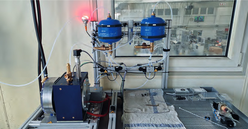
The Konzelmann endurance test stand for load spectra of oil temperatures of up to 120 °Celsius
A consultative approach
Thus, for the first time, a valve has been developed that optimally functions during the critical phase of water crossings, ensuring that the membrane remains unclogged with oil. All gearboxes available on the market can be tested in advance and manufacturers can be advised optimally.
This groundbreaking product innovation is adaptable to all vehicle types and drivetrains, even within mobile systems. It is characterized by its minimal installation requirements and space-efficient design. The precisely defined ventilation and exhaust mechanism guarantees optimal pressure management within transmissions and other systems. Additionally, the Pressure Equalization Element offers a distinct production advantage over conventional hose constructions: It enables vehicle rotation on the production line even after the transmission/e-axle unit has been filled with oil.
Currently, the product is already undergoing testing with an OEM, with production scheduled for 2024.
About Konzelmann
Konzelmann GmbH, headquartered in Löchgau between Stuttgart and Heilbronn in south-western Germany, develops and produces high-quality plastic injection molding products. For more than 60 years now, Konzelmann has planned, developed, and manufactured high-precision components and complex assemblies made of polymeric materials for the medical, automotive and industrial sectors. Their extensive experience has made them a market leader in the fields of highly specialized technical applications. Furthermore, Konzelmann has a global presence, with representatives in Detroit/USA, Seoul/Korea and New Delhi/India.
More information: https://www.konzelmann.com/en/expertise

JTEKT Ultra Compact Products for Further eAxle Improvement
Makoto NISHIJI, Chief Engineer Driveline CE Dep’t, Automotive Business Unit, JTEKT Corporation JTEKT contribution for e-Drive system The automotive industry is developing technologies to respond to the once-in-a-century transformation for realizing a carbon-neutral, recycling-oriented, safe and comfortable society. As the powertrains of automobiles become electrified, the requirements for the e-motor based driveline systems and units […]
Continue reading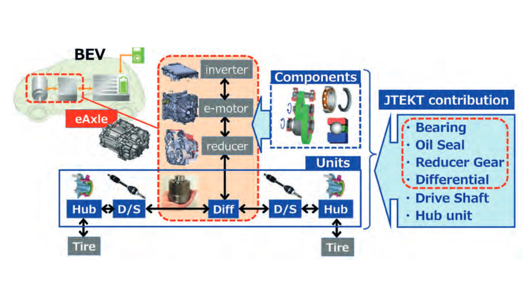
JTEKT Ultra Compact Products for Further eAxle Improvement
Makoto NISHIJI, Chief Engineer Driveline CE Dep’t, Automotive Business Unit, JTEKT Corporation
JTEKT contribution for e-Drive system
The automotive industry is developing technologies to respond to the once-in-a-century transformation for realizing a carbon-neutral, recycling-oriented, safe and comfortable society. As the powertrains of automobiles become electrified, the requirements for the e-motor based driveline systems and units that handle the vehicle movement are changing significantly. To take this evolution to an even higher level, reliability and cost reduction are essential, but it is also important to address improvements such as better power consumption (loss reduction, weight reduction, efficient regenerative braking), mountability (size reduction), low NV, and added values (4WD function, Torque control devices, etc.). To achieve this, JTEKT is conducting technological development for e-Drive system by several units/components aiming for “No.1 & Only One” in each field. (Fig. 1)
eAxle improvement by JTEKT Ultra Compact products
Following to the strong demand for higher power density eAxle in future, JTEKT has developed “Ultra Compact” product series, covering Differential (JUCD), Ball Bearing (JUCB) and Conductive Ball Bearing (JUEB), Oil Seal (JUCS) for eAxle size and weight reduction.
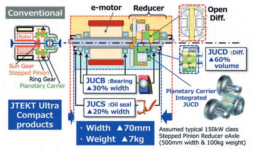
Figure 2: Co-Axial eAxle with JTEKT Ultra Compact products
Fig. 2 shows application example for 150kW class Co-Axial stepped pinion reducer eAxle. Co-Axial eAxle has advantage for packaging in height and front-rear axial length, therefore higher power density compared with traditional 3-Axis parallel offset reducer eAxle, but the eAxle width remains wide because of side-by-side e-motor, reducer, and differential layout. By introducing JTEKT Ultra Compact products, we estimate -70mm width and -7kg weight reduction from typical Co-Axial eAxle arrangement, therefore we can contribute eAxle power density improvement furthermore.
JUCB® Features and Advantages: Compact and High-speed performance
The most important requirement for bearings due to the shift to BEVs is higher rotational speed. In some cases, the maximum rotational speed ratio between the conventional power source, the engine, and the motor can exceed more than three times. The problem is the deformation of the cage due to centrifugal force. With a typical resin cage, when the limit speed is exceeded, the cage pockets deform due to centrifugal force, causing interference with the rolling elements, and the increased rotational resistance causes abnormal heat generation, leading to seizure.
JTEKT has developed a combination cage concept that can minimize deformation. Two resin parts of the same shape are combined to create a structure that suppresses deformation of each other, ensuring cage strength. Furthermore, in order to downsize, JTEKT have developed a bearing, JUCB® (JTEKT Ultra Compact Bearing®), which reduces the bearing width to almost the ball diameter size by minimizing the cage width (Fig. 3).
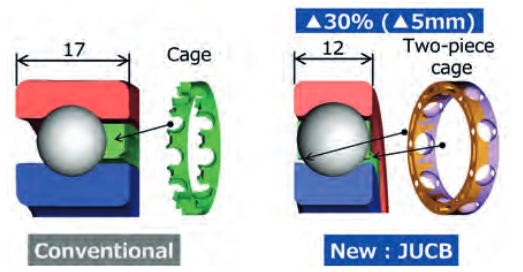
Figure 3: JUCB® (JTEKT Ultra Compact Baring®)
By optimizing the cage mold and that conditions, JTEKT achieved high-speed rotation of over 2 million dm-n (bearing high-speed performance index: multiplication of ball pitch diameter (dm) and rotational speed) under oil lubrication.
 UEB® Features and Advantages: Compact and Conductivity
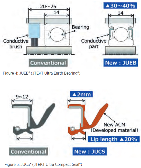
In bearings used in motors (especially driven by inverters), a potential difference may act between the inner and outer rings of the bearing due to magnetic flux imbalance inside the motor. Sparks (electrolytic corrosion) are generated at the contact between the rolling elements and the raceway due to this potential difference, which is known to cause washboard-like damage to the raceway. Conventional technology has taken measures to insulate bearings, such as using ceramic balls as insulators and forming an insulating coating on the outer ring surface. In addition, measures have been put into practical use to bypass the potential between the tracks other than the bearings using a separate circuit parallel to the track. JTEKT has developed JUEB® (JTEKT Ultra Earth Bearing®), which uses a conductive material in the seal to bypass the current path to the seal and avoid electrolytic corrosion on the bearing raceway. JUEB will provide a compact bearing with a conductive mechanism, contributing to improving the reliability of eAxle. (Fig. 4).
JUCS® Features and Advantages: Compact and Sealability
The oil seal installed at the connection between the differential and the drive shaft must be able to prevent oil leakage from the inside and contamination from the outside. If the seal width is shortened to make the seal smaller, the lip length will also become shorter, and if the conventional design is used, the ability to follow eccentricity to the shaft will decrease. In addition, the rubber will become hard at low temperatures, worsening the ability to follow the eccentricity. As a result, there was a problem that oil leaks were more likely to occur.
We have developed an acrylic rubber material with improved low-temperature properties and have improved its ability to follow eccentricity at low temperatures by optimizing the tension force composition ratio (rubber, spring). The acrylic rubber also has improved elasticity and can maintain the same oil retention capacity as conventional products. As a result, the JUCS® (JTEKT Ultra Compact Sael®) makes it possible to shorten the seal in the axial direction, contributing to the miniaturization of e-axles. (Fig. 5).
JUCD® Features and Advantages: High torque density and safety performance
Compared to typical bevel gear type open differential, JUCD® (JTEKT Ultra Compact Diff®) has an increased gear mesh quantity and wider gear mesh width at larger gear mesh diameter between planet gear (PG) and side gear (SG). This is possible by using small diameter parallel axis planet gears which are directly supported by the housing bore similar with journal bearing structure. As a result, JUCD has higher torque density (= strength/volume) than typical open diff. Required differential gearing functional volume for JUCD will be less than half compared with open diff. for the same strength. (Fig. 6)
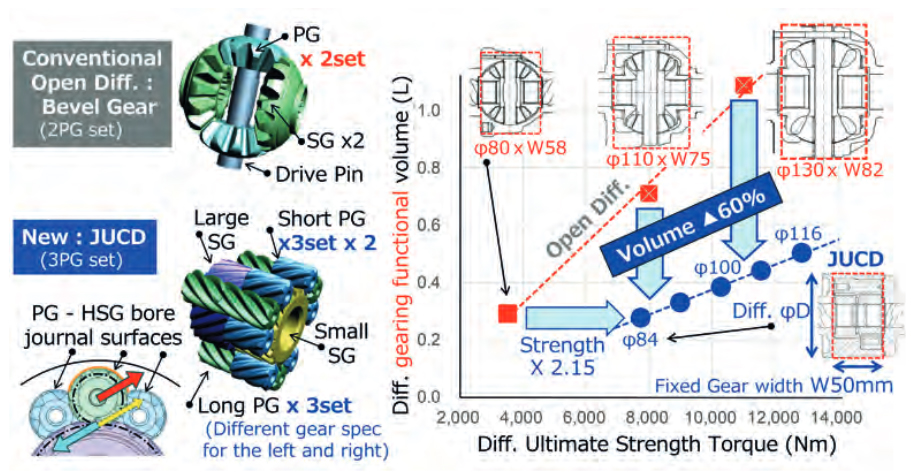
Figure 6: JUCD® (JTEKT Ultra Compact Diff.®
PG outer diameter – HSG bore direct contact structure generate torque sensing limited slip diff effect, which brings vehicle performance improvement advantages for safe and confident drive under daily various driving situations. This LSD function works not only drive mode, but also coast mode or even regenerating braking mode, therefore it will bring potentially better power consumption for BEV in real world by minimizing wheel slip/spin situation and friction brake activation.
Planetary Carrier integrated JUCD
In case of Co-Axial stepped pinion reducer, planetary carrier and differential housing will have same rotational speed, therefore it is possible to integrate those two functions into one housing, but typical open diff. bevel gear will be located at the side of planetary carrier in to avoid radial dimensional interferences and maintain assembly possibility of the differential components into one-piece housing thru its window. (Fig. 2)
JUCD can reduce differential radial and axial dimension significantly keeping the same required strength. By using this advantage, it is possible to locate the differential well inside of the planetary reduction gearing for reducer width improvement by full axial overlap.
On top of JUCD, JUCB and JUCS could be also integrated into the reducer for further width/weight improvement not only for reducer, but also for eAxle, and even vehicle level. (Fig. 7)
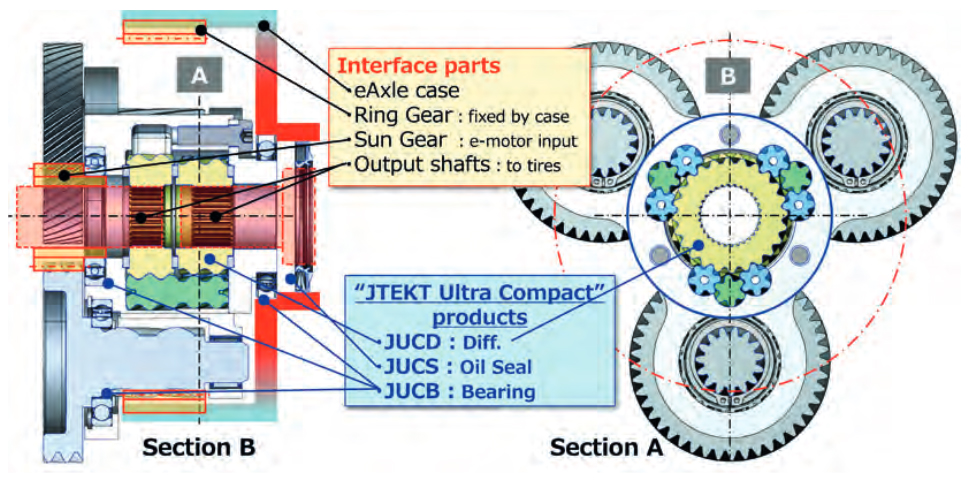
Figure 7: Planetary carrier integrated JUCD in eAxle reducer
Cylindrical JUCD housing together with the same number of differential PG set and reducer stepped pinion gear set reduce planetary carrier stress variation at each stepped pinion support during torque transfer situation. This is also interesting advantage to minimize tooth contact variation of the stepped pinion set, so that it will be easier to define common and optimum tooth micro geometry for the reducer gearing for low NV, and better durability.

HOERBIGER innovative solutions for electric drive trains
Your reliable system and component supplier for future mobility From development to production of innovative components and complete systems for conventional and alternative powertrains – HOERBIGER offers you everything from a single source. The portfolio for electrified drive trains includes transmission synchronizers and innovative shift elements for coupling and decoupling as well as components and […]
Continue reading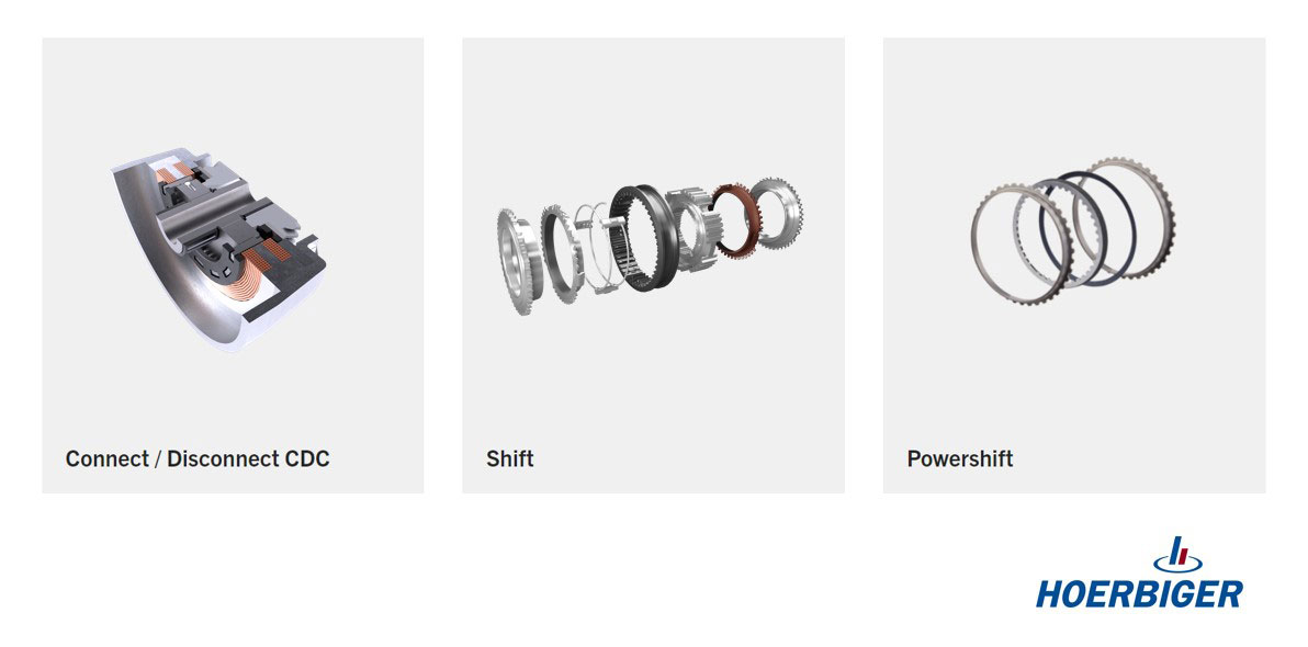
HOERBIGER innovative solutions for electric drive trains
Your reliable system and component supplier for future mobility
From development to production of innovative components and complete systems for conventional and alternative powertrains – HOERBIGER offers you everything from a single source. The portfolio for electrified drive trains includes transmission synchronizers and innovative shift elements for coupling and decoupling as well as components and clutch assemblies.
The emDOC, one of the new products from HOERBIGER, is an efficient electromagnetic comfort dog clutch for connect/disconnect or multi-speed in HEV and BEV powertrains. It offers an intelligent sensor technology and control for maximum comfort and NVH requirements. The smart 2 in 1 solution of a dog clutch coupling and an intelligent actuator reduces installation space and costs by eliminating external mechanics.
With eSYN you have best NVH behavior and efficiency thanks to a newly developed pre-synchronizer unit that uses annular springs to fix the synchronizer rings axially and radially, thus preventing oscillation and the associated rattling noise. Increased power density due to reduced switching distances and times and up to 10% less installation space. Friction lining is possible in caron, sinter or steel.
The Dog clutch offers you more performance for automated shifting and decoupling operations. Thanks to a spline geometry the system improves shift dynamics and noise comfort (NVH).
Furthermore, HOERBIGER is your reliable system partner for clutch assemblies with comprehensive know-how in tribology and friction lining technology for best performance. Steel-, friction and end plates come from a single source. Thanks to the different friction linings developed and produced in-house and the extensive expertise in special surface treatment, HOERBIGER offers solutions optimized for your application.
https://www.hoerbiger.com/de/produkte-and-services/komponenten-fuer-elektrischen-antriebsstrang.html