12 Deep Dive Sessions on Passenger Cars and Commercial Vehicles
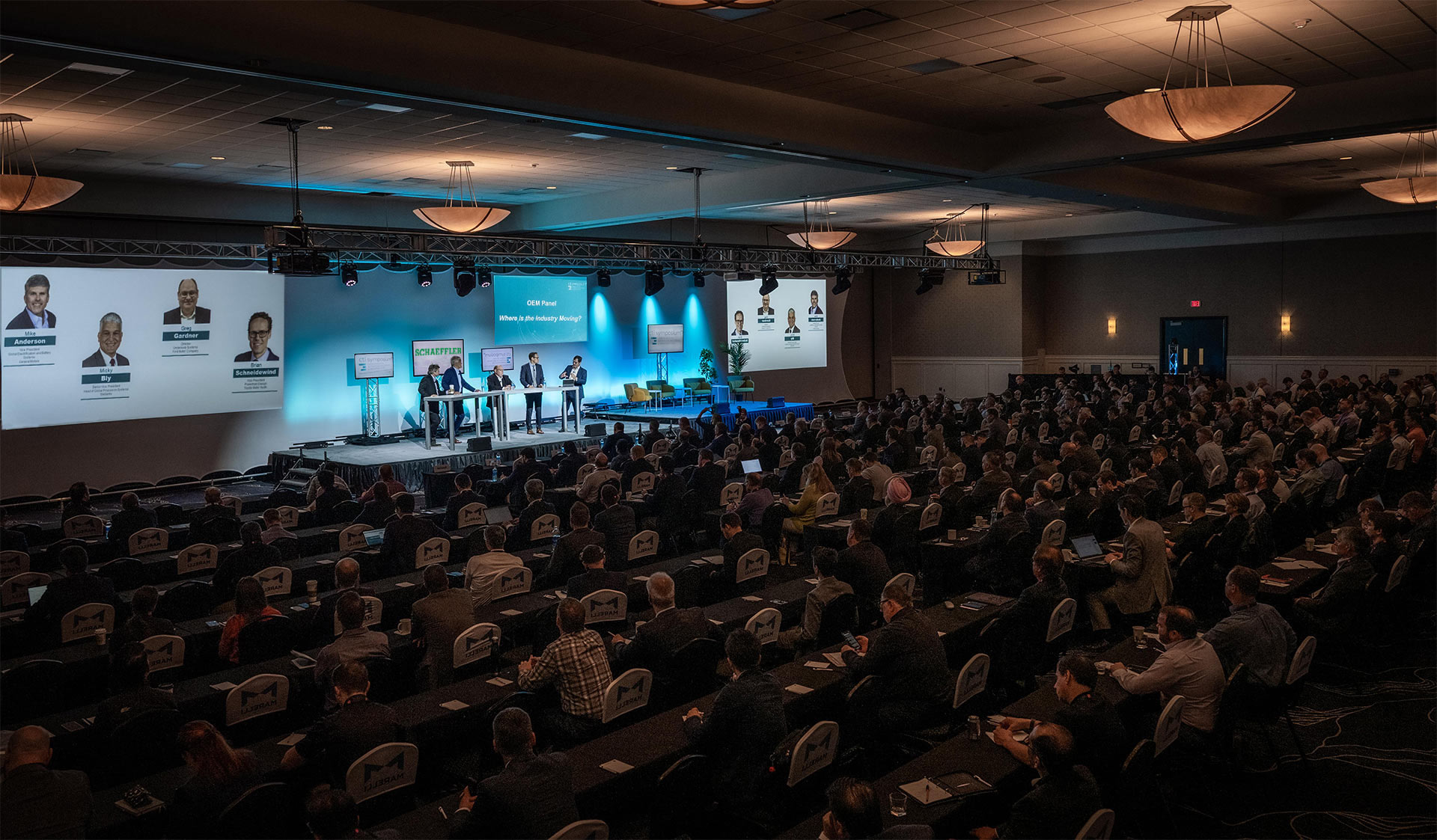
OEM Panel: “What´s coming next?“
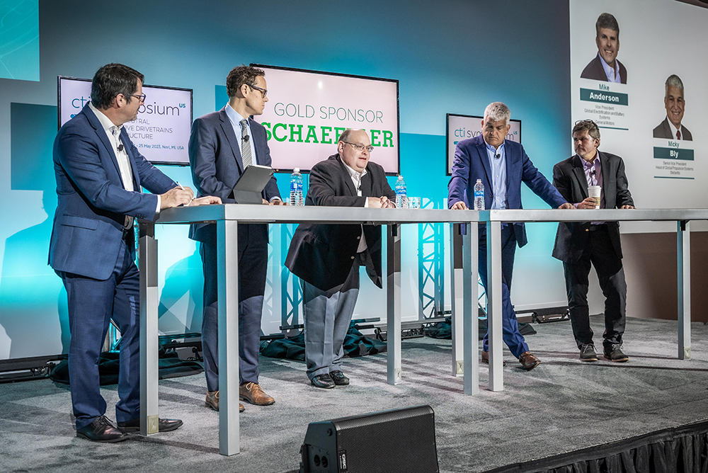
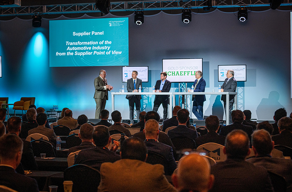
Supplier Panel: “How deal with the Supply Chain, Sustainability & Accessibility Requirements and Challenges“
University Panel “EV Technologies of the Future – University Projects & Perspectives”
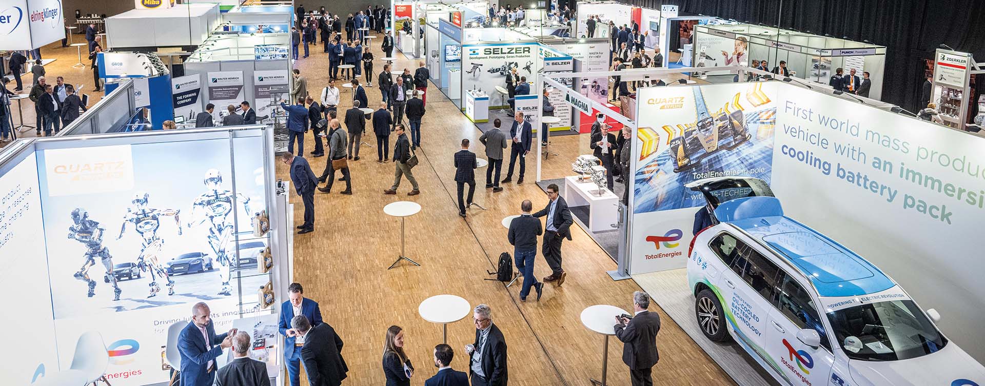
Explore the latest products and innovations in the accompanying exhibition
Ride & Drive: Enjoy a full-feature tech experience in series and demo vehicles
CTI & AWAF Female Power Up Morning Session
Topics
Transformation of the Automobile and Supplier Industry
Markets and Analysis
Latest EV and HEV Propulsion Technology
E-Drives, E-Motors
EDU Components
Power Electronics
Thermal Management
Battery Technologies
Lubrication
Development Tools
The Expert Summit for a Sustainable Future Mobility
Only together we can create a sustainable future mobility. CO2 reduction is critical for automotive drivetrain. Here the battery electric drive using renewable energy is the focus. What can we do to increase efficiency and reliability, reduce cost and at the same time reduce the upstream CO2?
At CTI SYMPOSIUM the automotive industry discusses the challenges it faces and promising strategies. Latest solutions in the fields of electric drives, power electronics, battery systems, e-machines as well as the manufacturing of these components and supply chain improvements are presented. For the bigger picture market and consumer research results as well as infrastructure related topics supplement the exchange of expertise.
CTI SYMPOSIA drive the progress in individual and commercial automotive transportation. Manufacturer, suppliers and institutions are showing how to master the demanding challenges.
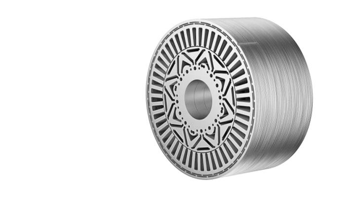
ElringKlinger MetaloBond™ is a lamination stack technology using a full face glue system with high sealing capability to support direct rotor and stator cooling for increased e-motor performance. With increasing rotation speed and less installation space in advanced electric engine concepts, heat becomes more and more an issue.
ElringKlinger MetaloBond™ is a lamination stack technology using a full face glue system with high sealing capability to support direct rotor and stator cooling for increased e-motor performance.
With increasing rotation speed and less installation space in advanced electric engine concepts, heat becomes more and more an issue.
The best way to cope with this issue is to avoid heat generation by reducing electromagnetic losses, e.g. in the iron core. A further important approach is to use an efficient direct cooling system to get heat out of the system and therefore increase continuous performance of the electric motor significantly.
ElringKlinger is very experienced to produce materials < 0.30 mm. The target is to reduce the eddy current losses in the system and by doing so, reducing the generated heat.
The packages produced with the MetaloBond™ technology achieve good values in strength and setting behavior.
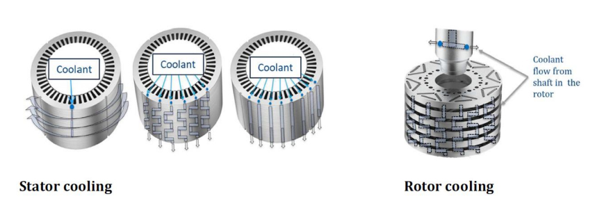
As a further approach, a direct cooling system can be used to remove heat. If the direct cooling system shall be designed within the iron core, a reliable and lifetime durable sealing between the single layers of the iron core must be ensured.
The ElringKlinger MetaloBond™ technology guarantees a high sealing capability. Due to its clear focus on sealing performance, it allows more design freedom versus other full face glue systems on the market.
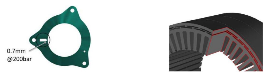
With MetaloBond™ made by ElringKlinger, cooling channels can be placed with a minimum distance to the perimeter and still seal pressures up to 200 bar, even under thermal cycling and thermal shock conditions.
This allows to place cooling channels where they are needed. Either close to the hot spots or close to the perimeter to reduce interruption of magnetic flux. The result is an efficient cooling system with an increase in continuous performance.
As a full-service supplier, ElringKlinger is able to support you with the full range of services from heat flux calculation, lasered and stamped prototypes to fluid flow testing with thermal cycling or shock.
We are looking forward to meet you at our booth no. A7 at CTI in Novi!
A smart way to meet the service fill requirements of multiple OEM specifications. OEMs in North America are increasingly fitting stepped automatic transmissions with eight or more speeds into their light-duty vehicles as they look for fuel economy improvements. However, the wide variety of different types of transmissions in the light-duty parc means the number […]
A smart way to meet the service fill requirements of multiple OEM specifications.
OEMs in North America are increasingly fitting stepped automatic transmissions with eight or more speeds into their light-duty vehicles as they look for fuel economy improvements. However, the wide variety of different types of transmissions in the light-duty parc means the number of fluids required to meet the full range of service fill requirements is expanding. This article explains how multi-vehicle driveline fluids, formulated to meet a wide range of OEM specifications, can bring a number of benefits to this increasingly complex market.
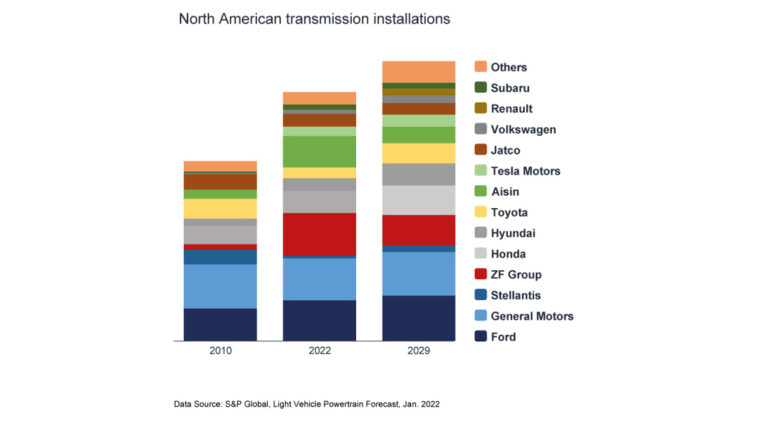
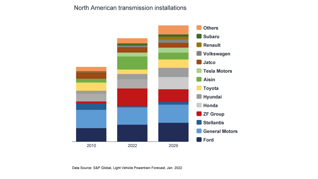
The North American light-duty vehicle parc is continuing to grow – reaching an all-time high of more than 280 million in 2022. And, as OEMs look for technology to help improve fuel economy, the number of different types of transmission in use is also continuing to grow. Over time, as fuel economy mandates have been tightened, the market has transitioned away from the once popular four, five and six speed automatic transmissions and is now dominated by those with eight or more forward speeds. The average age of light-duty vehicles in operation in this region is reported to have risen to more than 12 years. This means there are a huge number of vehicles in the market with vastly different service fill transmission fluid requirements.
An interesting trend we are seeing in this region is the increase in the number of installations from OEMs outside of North America, in particular from Japan and Europe. In addition, transmission hardware is now even more complex and compact than in the past.
This diversification means that along with the JASO 1-A 13 and 1-A 13-LV, that combine critical elements of several OEM specifications into one, there are a growing number of OEM fluid specifications designed to ensure the continued protection of their specific transmissions.
North American service fill market
Changes in the vehicle parc mean the demand for service fill fluids in North America is continuing to evolve.
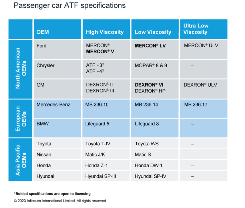
Over the years we have seen, and continue to expect, a steady decline in the use of GM DEXRON® III, Ford MERCON®/MERCON®V and Chrysler ATF+4® automatic transmission fluids (ATF). These tended to be higher viscosity fluids that covered older vehicles, most of which are now out of warranty.
On the growth side, we expect to see more demand for both DEXRON®VI and MERCON®LV low viscosity fluids.
The growing numbers of import vehicles with different OEM ATF specifications make a multi-vehicle solution attractive, especially for vehicles out of warranty. This is especially the case for quick lube and service shop operations that need to service a wide range of vehicles without carrying stock of multiple fluids. And, not surprisingly, we can see exciting opportunity and growth in this multi-vehicle transmission fluid market segment.
The benefits of multi-vehicle fluids
Currently more than 100 ATF types are available in the North American market. This proliferation means a single multi-vehicle fluid can offer significant advantages to users looking for versatility, performance and convenience for light-duty applications. It is understandable that there is some scepticism around the use of multi-vehicle ATF since it is not licensed. However, Infineum products have been proven in the market, successfully delivering a fine balance of friction and oxidation control on the road in consumers’ vehicles for more than 10 years.
Infineum multi-vehicle ATF cover 99% of all the latest and legacy light-duty planetary gear transmissions on the roads today.
Multi-vehicle fluid technology is designed to cover the needs of the ageing and diversifying North American car parc. In terms of its advantages, it delivers the balanced frictional performance and hardware protection for the latest domestic and import transmissions, provides exceptional performance in older designs and acts as the perfect complement to OEM licensed ATFs.
Multi-vehicle ATF is formulated with advanced additives that help protect against wear, oxidation, and deposit formation. It can also provide smooth shifting and consistent performance across a range of temperatures. This can extend the life of the transmission as consumers keep their vehicles for longer and longer.
The single additive package can be used to blend in high and low viscosity formulations without sacrificing hardware protection and delivers performance attributes including:
Friction control: finely tuned to enable balanced torque transfer and smooth shifting
Friction durability: maintain anti-shudder durability enabling smooth acceleration over time
Oxidation stability: increase oil life and reduce sludge
Shear stability in high and low viscosity environments
Infineum has run a comprehensive test programme, including field, dynamometer and rig tests, in a range of different transmissions to assess multi-vehicle fluid advantages in some of the key performance areas and to prove all the various ATF applications.
Opportunities for growth
Formulation flexibility is of growing importance, particularly as base stock supply remains tight and prices volatile. Here Infineum products can be formulated in many Group III base stock options, or Group II & III base stock systems with up to 50% Group II. In addition, as consumers look for more sustainable product options, this formulation flexibility has enabled us to start to integrate both re-refined and bio-based base stocks into our driveline portfolio. Also, having a dynamic single fluid that satisfies a range of vehicle needs can contribute towards sustainability goals via the simplified logistics, storage, and handling required to get the right fluid to the right service areas.
Clearly, low viscosity multi-vehicle ATFs can offer significant advantages to users looking for a single fluid to cover a range of light-duty applications. They not only deliver the balanced frictional performance and hardware protection for the latest domestic and import transmissions and provide additional protection to older transmissions but also give blenders the flexibility they need to meet the requirements of all their target markets.
Infineum multi-vehicle fluid technology performance is proven in millions of transmissions currently on the road.
Proven multi-vehicle ATFs provide fluid marketers with a strong customer value propositions including reduced stock holding, increased flexibility and less potential for misapplication and offer an exciting opportunity for future growth in North America and potentially beyond.
Progress never stops. With electric drive technology evolving rapidly, developers can now meet customer requirements even more precisely and comprehensively, while higher efficiency also increases the performance and range of battery-electric drives. So what’s next? One thing’s for certain: With customers seeking more independence and flexibility, plug-in hybrid drives are staging a comeback.
Progress never stops. With electric drive technology evolving rapidly, developers can now meet customer requirements even more precisely and comprehensively, while higher efficiency also increases the performance and range of battery-electric drives. So what’s next? One thing’s for certain: With customers seeking more independence and flexibility, plug-in hybrid drives are staging a comeback.
CTI Symposium USA – covering all the angles with the customer in mind
In twelve Deep Dive sessions, specialist lectures will cover the latest electric drive systems and their key components. In the plenum, prominent representatives from OEMs, suppliers and universities will discuss their strategies and technologies for tomorrow’s CO2-neutral mobility. The goal: Advanced automobiles that, ultimately, only need to convince one person – the driver.
Raising many bars. And clearing them all.
“With our next generation eDrives, Magna aimed to set new standards in KPIs such as efficiency, power-to-weight, torque-to-weight, power-to-price and torque density,” says Daniel Lindvai-Soos (Magna Powertrain, Austria). Further goals included a drop-in solution on the hardware and software level, higher product and production sustainability, and improved system integration. As the key figures he presents will show, the company has certainly succeeded.
Magna’s NextGen drive is significantly lighter and smaller than the current version. The 29% reduction in the Z-dimension is particularly important, since it enables horizontal and vertical integration into the rear and front vehicle space. The new drive offers 94% efficiency in WLTC, and 93% including real-world highway driving. This improves efficiency over a wide speed range, and expands application flexibility. The new eDrive uses significantly less aluminum and rare earth material, and the CO2eq for production has been cut by around 25%. Among the new technologies making their debut in the NextGen drive are the HV Embedding SiC Power Modules. These reduce electrical losses and improve efficiency. Daniel Lindvai-Soos will also be giving an overview of software-oriented advantages such as OPP (optimized pulse patterns), the thermal operating strategy, active peak load damping, state-of-health monitoring, and other end-user functions. A digital twin is part of the new Magna NextGen drive. It simplifies integration into the operational strategy, and supports the ‘drop-in solution’ approach.
“What could we do better?” How Toyota learns from its competitors.
Space is a valuable commodity in battery electric vehicles (BEVs), and customers want vehicles whose drivetrain components all combine high performance with efficient use of space. The study presented by Jaret Villarreal (Toyota, USA) will focus on the power density potential of compact, single-axle powertrain systems. The study began by reverse-engineering a competitor’s geartrain. Using this model, an in-house optimization workflow then explored the feasibility of reducing its size further, without compromising on standards.
Jaret Villarreal will provide insights into the workflow and software used, and will discuss the results of the optimization. The study clearly demonstrates the possibility of considering optimization at earlier development stages for BEV transaxles, and also highlights the need for continuous improvement. Using the latest technological advances, Toyota engineers can now pursue multiple competing goals simultaneously, all in specific workflows. These include efficiency, NVH, durability, size and cost. As a result, they can create designs that offer customers the best possible driving experience.
Control losses with high-speed motors?Not with Surface Acoustic Wave (SAW) sensors.
There is a growing trend towards high-speed, high pole count motors. But to maintain controllability, they require higher switching frequencies from the power electronics. As David Hind (Drive System Design, UK) and Ryan Maughan (Transense Technologies, UK) will explain, current solutions can quickly reach their limits here. Field Oriented Control (FOC) has a high computational burden, while Direct Torque Control (DTC) suffers from the poor accuracy of the torque estimators used.
David Hind and Ryan Maughan will be presenting a new method that uses SAW (Surface Acoustic Wave) sensor technology to overcome these shortcomings. By embedding SAW sensors, developers can obtain robust, precise, high-speed readings of torque and shaft temperature in real time. SAW sensor technology has already proven itself in motorsport and aviation, and is suitable for use in production motor drive systems. “Transense Technologies has been working with Drive System Design (DSD) to explore the potential of integrating torque sensors into the control loop of electric motors,” say Ryan Maughan and David Hind. “Using DSD’s extensive simulation capabilities, new control algorithms can be implemented and assessed.” The speakers will discuss the findings of this work, and will demonstrate an improved method of motor control using SAW torque measurement feedback. Specifically, they will quantify the reduction in computational overhead compared to FOC. This can indicate what increase in inverter switching frequency – and hence potentially motor fundamental frequency – can be achieved from a motor control perspective.
Torque management systems – the masters of traction and driving dynamics
For maximum driving pleasure and safety, ample torque alone is not enough. You also need to distribute that torque optimally between the wheels and axles and convert it into traction, always in line with specific driving scenarios. Modern electric drives can use various torque management systems (TMS) to achieve this aim. But which works best in which specific case?
This is the question that Josefin Frisk (BorgWarner, Sweden) will be addressing in her lecture. As EV models become more diverse, the range of drive architectures for different segments and performance levels is expanding too. In the past, several TMS implementations have been proposed – one electrical machine per wheel, for example, or an additional electrical machine to supply differential torque, carefully actuated friction clutches to replace the differential, or an electrically controlled limited-slip differential. All these TMS architectures provide additional degrees of freedom for the vehicle controls. They also affect energy consumption and performance in different ways, change how the vehicle feels for the driver, and how it performs under challenging driving conditions. In addition, they offer potential for differentiation, and significantly improve safety. As you might expect, each architecture involves an inherent trade-off. In her presentation, Josefin Frisk will quantify and explain the differences between various TMS options for BEV architectures in terms of energy consumption, vehicle performance, packaging and cost. And in the process, she will answer the question we asked at the beginning.
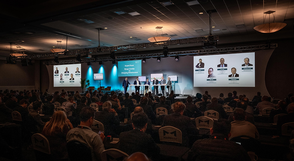
A surprising comeback: What’s next for hybrid drives?
There’s no missing the resurgent interest in hybrid drives, as a glance at our agenda at CTI Symposium USA will confirm. With high-ranking representatives from leading OEMs, the panel discussion on this topic promises to yield interesting insights. In the plenary session, hybrid pioneer Toyota will be sharing details of its development work on the new hybrid system for the Camry. And last but not least, hybrid drives will feature in individual contributions to the Deep Dive sessions.
Advanced hybrid systems – the best of both worlds
There are good reasons to favor hybrid drives as a bridging technology. As Aditya Dattawadkar (Schaeffler Group, USA) will point out, most US customers want an electric vehicle that won’t make them alter their lifestyle too much. They are used to driving big vehicles for hours on end with just short breaks before they resume their journey. By offering the flexibility customers seek in terms of range and energy sources, hybrids tick all these boxes and deliver the best of both worlds: ICE and BEV.
Business-wise, hybrid vehicles are the ideal way to keep using existing technologies while simultaneously promoting the switch to pure-electric drives. Some engines and transmissions are the result of decades of development work, and are highly efficient, cost-effective and reliable. As Aditya Dattawadkar will explain, Schaeffler is working hard on hybrid systems that can be flexibly adapted to customer needs. The company benefits from the knowledge gained from ICE drivetrains, and also from advances in electric motor development. Schaeffler has several ideas in production, and more at advanced stages of development. In his lecture, Aditya Dattawadkar will showcase some of the latest hybrid vehicle technologies, then address the growing demand for hybrid systems and show ways in which it can be met. His application fields will range from passenger cars to pickup trucks and light commercial vehicles.
Integration in perfection – a pioneering approach for a PHEV P3 pickup truck
What’s the best way to integrate a high-performance P3 hybrid system in a 4WD light truck? The research paper presented by Larry Pritchard (BorgWarner, USA) gives a surprising answer: “Put it in the transfer case!”
This innovative integration approach eliminates the need for conventional planetary transfer case range sets, and significantly simplifies packaging. The primary goal of the research study was to enhance the electrical proficiency of these hybrid systems, and specifically to extend their electric-only range. The aims are to reduce reliance on combustion engines, and to achieve higher levels of electrification. The optimized sizing of electric drive train components, including 400 and 800 volt systems, plays an important role.
Larry Pritchard will present key advantages and interesting technical highlights of the P3 hybrid drive system. These include on-demand front axle braking energy recoupment, which the integration of the P3 system into an active transfer case makes possible; using the hybrid drive as a power generator and energy source at remote worksites, and the fact that a PHEV P3 pickup truck can meet ambitious emissions targets. The research will help developers to build efficient, versatile light trucks that satisfy users to the full in terms of driving performance, independence and sustainability.
CTI Symposium USA – three days that make a difference
Discover an informative and inspiring program on May 15th and 16th! Follow the specialist lectures in twelve Deep Dive sessions. Play an active role in the plenary discussions, and explore the latest developments at CTI SYMPOSIUM EXPO. Enjoy a test drive with CTI RIDE & DRIVE – and grow your business network at our CTI NETWORKING NIGHT.